Building Acoustics
Indirect Air-Borne Transmission
8
Indirect Air-Borne Transmission
by J.J.M. Cauberg, A. Schuur and M.J. Tenpierik8.1
Introduction
Indirect air-borne transmission could be defined as flanking sound transmission from one room to another via an air volume that borders on the partition wall (Figure 8.1). Contrary to what is regularly and officially called flanking sound transmission (=indirect structure-borne transmission), the sound does not
propagate via construction elements but via an air volume. This air volume can be a ventilation duct, the air space above a suspended ceiling or below a raised floor, a corridor or an atrium.
In this chapter, indirect sound transmission via such air volumes will be treated.
8.2
Coupled Rooms
The sound propagation via an indirect air volume, like an atrium, can acoustically be described with the regular equations assuming diffuse sound fields in all rooms. The sound transmission from the sending room towards the atrium then equals
1 ; ; 1 10log p atrium p s atrium S L L R A = − + (8.1a),
while the sound transmission from the atrium towards the receiver room is described by
2 ; ; 2 10log p r p atrium r S L L R A = − + (8.1b).
The sound pressure level difference between the sending and the reciever room can now be obtained from combining previous equations. It equals
1 2 ; ; ( 1 2) 10log p s p r atrium r S S L L R R A A − = + − (8.2), with
Lp;atrium = the sound pressure level in the atrium [dB]
Lp;s = the sound pressure level in the sending room [dB]
Lp;r = the sound pressure level in the receiving room [dB]
S1 = the surface area of the partition wall between sending room and atrium [m2]
S2 = the surface area of the partition wall between atrium and receiving room [m2]
R1 = the air-borne sound insulation of partition wall S1 [dB]
R2 = the air-borne sound insulation of partition wall S2 [dB]
Aatrium = the sound absorption of the atrium [m2 sabin]
Ar = the sound absorption of the receiving room [m2 sabin]
In practice, the term 10 log S1S2/AatriumA2 will easily be about -10 to -15 dB. With a closed interior façade
thus, even if it is a full glass façade, the sound pressure level difference between sending and receiving room will easily be around 60 dB. The coupling of both rooms via an atrium will only be of practical importance if the interior walls towards the atrium are of bad acoustic quality because of for instance opened windows. In that situation it is especially the sound absorption in the atrium, Aatrium, which has to
limit the sound transmission. In practice this is translated into a requirement for a maximum reverberation time of the atrium; this latter requirement is by the way also needed to achieve a good and comfortable acoustic environment in the atrium itself. Generally it is set to be 1.5 to 2.5 s at most.
Figure 8.1 – Transmission of sound from one room to another via an atrium (cross-section).
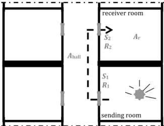
Figure 8.2 – Transmission of sound from one room to another via a corridor (plan).
In case of two adjacent rooms connected to a corridor, indirect sound transmission via the door of the sending room, the corridor and the door of the receiver room might occur. If both doors are close to one another or are oriented 90o from each other, the sound pressure level difference between sending and
receiving room (Lp;s - Lp;r) calculated according to equation (4.2) will in practice be about 2 dB lower. In
standard NEN 12354-1 (2000) therefore a correction factor cdoorposition is introduced resulting in the
following equation 1 2 ; ; ( 1 2) 10log p s p r doorposition corridor r S S L L R R c A A − = + − + (8.3).
The value of this correction factor equals 0 dB for doors which are far apart from each other and -2 dB for doors which are lying closely together or see each other at an angle of 90o.
S1 R1 S2 R2 Ar Ahall sending room receiver room S1 R1 S2 R2 Ar Aatrium sending room receiving large atrium
8.3
Ventilation ducts
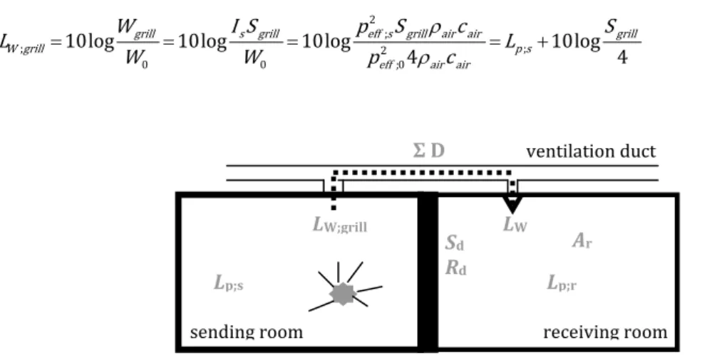
Figure 8.3 gives an impression of the sound propagation between two rooms via a ventilation duct. We assume that the opening of the ventilation duct in both rooms is located in a diffuse sound field. Resulting from a sound pressure level in the sending room, Lp;s, a sound power level LW;grill arises in the grill of the
ventilation opening ; 0 10log grill W grill W L W = (8.4), with
W0 = the reference sound power (=10-12 W)
Wgrill = the sound power in the grill of the ventilation opening [W].
This latter sound power can be calculated from
grill s grill
W =I S (8.5),
with
Is = the sound intensity of the diffuse sound field in the sending room [W/m2]
Sgrill = the surface area of the ventilation opening [m2]
From room acoustics we now that the sound intensity in a diffuse sound field equals
2 ; 4 eff s s air air p I c ρ = (8.6), With
P2eff;s = the effective sound pressure of the diffuse sound field in the sending room [Pa]
ρaircair = the specific acoustic impedance of air (=410 kg/(m2s) at 20oC)
Combining equations (4.4) to (4.6) thus gives us the sound power level in the grill of the ventilation opening
2 ;
; 2 ;
0 0 ;0
10log 10log 10log 10log
4 4
grill s grill eff s grill air air grill
W grill p s
eff air air
W I S p S c S L L W W p c ρ ρ = = = = + (8.7).
Figure 8.3 – Transmission of sound from one room to another via a ventilation duct (cross-section).
Sd Rd Σ D Lp;s ventilation duct LW;grill LW receiving room sending room Lp;r Ar
Via the ventilation duct, a sound power level, LW, is radiated from the ventilation opening to the receiver
room. This sound power level equals
; W W grill
L =L −
∑
D (8.8),with
ΣD = the total dampening of sound in the ventilation duct between both rooms [dB].
The sound pressure level in the receiving room resulting from the sound power radiating from the ventilation opening, Lp;r;duct, now equals
; ; 10log 4 ; 10log 4 p r duct W W grill r r L L L D A A = + = −
∑
+ (8.9), WithAr = the total sound absorption in the receiving room [m2 sabin].
Combining equations (4.7) and (4.9) yields
; ; ; 10log grill p r duct p s r S L L D A = −
∑
+ (8.10).As we have seen in previous chapters, the direct sound transmission between sending and receiving room via the partition wall can be obtained from
; ; ; 10log d p r direct p s d r S L L R A = − + (8.11), in which
Rd = the air-borne sound insulation of the direct partition wall [dB]
Sd = the surface area of the direct partition wall [m2].
Using energetic summation finally gives us the total sound pressure level in the receiving room, Lp;r, as
(
; ; /10 ; ; /10)
; 10log 10Lp r duct 10Lp r direct p r
L = + (8.12).
Equations (4.10) to (4.12) can also be written in a slightly different form introducing a resulting or total sound insulation between both rooms as
/10 /10 10log d10Rd grill10 D res d d S S R S S − − ∑ = + (8.13).
Using this equation, the sound pressure level in the receiving room can be obtained from
; ; 10log d p r p s res r S L L R A = − + (8.14).
For determining the dampening inside the ventilation duct resulting from acoustic lining inside ducts, different shapes, canal sizes, corner pieces, acoustic dampeners, inlet and outlet openings, and grills product information and information in literature should be used.
position along surface deq [m]
0.10 0.15 0.20 0.25 in a trihedral corner of the room
(where 3 surfaces meet) in a dihedral corner of the room (where 2 surfaces meet) in the centre of a surface
1.0 2.5 4.5 0.5 1.5 3.0 - 0.5 2.0 - - 1.0
Table 8.1 – Indicative values of Dinlet/outlet [dB].
As an estimate, the total dampening inside the ventilation duct can be written as a combination of the dampening of the duct itself, the corners and the inlet and outlet openings
duct corner inlet outlet
D= D + D +D +D
∑ ∑
∑
(8.15).The dampening inside the duct itself, of a corner and inlet/outlet opening can be estimated from
1.5 duct circumference D length surfacearea α ≈ (8.16a), 3/ corner D ≈ corner (8.16b),
Dinlet/outlet depends on the position along the surface and
on the equivalent diameter deq = √Sgrill;receivingroom (Table 8.1) (8.16c),
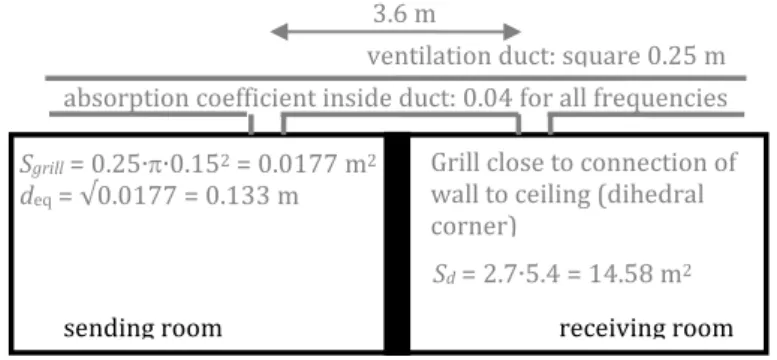
To get an idea of the influence of indirect sound via a ventilation duct on the total sound insulation an example with some estimated values is discussed briefly here. Figure 8.4 presents the details of the situation. Using equation (4.16a) we can calculate a dampening of 1.5∙0.04∙(4∙0.25/(0.25∙0.25))∙3.6=3.5 dB for the duct. Two corner pieces are located in this system; so, Dcorner equals 2∙3=6 dB. Using Table 8.1,
we can also estimate the dampening of the inlet and outlet opening as 1.8 dB each. In total we thus have an acoustic dampening in this system of 3.5+6+1.8+1.8= 13.1 dB.
Using (4.13) now we can compute the resulting sound insulation between both rooms if the sound insulation of the partition wall is given. Table 8.2 presents the results of this calculation for several values of Rd. Table 8.3 presents the result of a set of calculations for which additional acoustic dampeners are
inserted into the duct near the inlet and outlet openings. As can be seen, the higher the sound insulation of the partition wall is, the more apparent the influence of the transmission via the ventilation opening becomes. If the partition wall is acoustically bad, the indirect air-borne path is hardly observable and no additional measures are needed; if the partition wall is of high acoustical quality, the indirect air-borne path is quite apparent and additional measures are needed. Such acoustic measures can be acoustic dampeners installed in the duct system near the inlet and outlet opening. As can be seen from Table 8.3, they can drastically improve the sound insulation between both rooms.
Figure 8.4 – Example of indirect air-borne transmission via a ventilation duct (cross-section).
Sgrill = 0.25∙π∙0.152 = 0.0177 m2
deq = √0.0177 = 0.133 m
receiving room sending room
absorption coefficient inside duct: 0.04 for all frequencies 3.6 m
ventilation duct: square 0.25 m Grill close to connection of wall to ceiling (dihedral corner)
low values of Rd high values of Rd
Rd [dB] 22 30 35 40 45 50 55 60
ΣD [dB] 13.1 13.1 13.1 13.1 13.1 13.1 13.1 13.1 Rres [dB] 22.0 29.8 34.3 38.0 40.4 41.6 42.1 42.2
∆R [dB] -0.0 -0.2 -0.7 -2.0 -4.6 -8.4 -12.9 -17.8
Table 8.2 – Example of a calculation of the resulting sound insulation between two rooms with direct transmission and transmission via a ventilation duct (no dampeners).
Rd [dB] 40 45 50 55 60
ΣD [dB] 13.1 23.1 33.1 43.1 43.1 Rres [dB] 38.0 44.3 49.8 54.9 59.8
∆R [dB] -2.0 -0.7 -0.2 -0.1 -0.2
Table 8.3 – Example of a calculation of the resulting sound insulation between two rooms with direct transmission and transmission via a ventilation duct (additional dampeners).
8.4
Suspended ceilings
In the previous chapter, Table 7.1 showed the required sound insulation between two offices. The desire for flexibility, room acoustics and accessibility to building services often leads to a combination of movable lightweight partition walls and a sound absorbing suspended ceiling. In most cases the movable partition wall is connected to the underside of the suspended ceiling and not to the underside of the construction floor. As a result, an air cavity arises which connects both rooms, albeit separated by two times a
suspended ceiling. The sound transmission via the plenum above the ceiling then often is the weakest link in the total sound insulation. Not only does indirect transmission via the air cavity occur, also flanking transmission via the ceiling itself occurs. This latter sound transmission however is almost always negligible compared to the remaining transmission paths.
The simplified model according to Figure 8.5 presents the sound transmission via the plenum above a suspended ceiling qualitatively. The total sound transmission path can be split in two parts:
1. From the sending room to the fictive room partition surface in the plenum;
From the sending room sound energy is radiated into the plenum. The sound insulation of the suspended ceiling introduces a certain amount of sound reduction. Inside the plenum part of the radiated sound energy is absorbed and part is transmitted via the open connection in the plenum above the partition wall towards the plenum above the receiving room.
2. From the fictive room partition surface in the plenum to the receiving room;
The sound which arrives in the plenum above the receiving room is again partly absorbed. The remaining part transmits through the ceiling in the receiving room but before it reaches the receiving room it is also reduced by the sound insulation of the suspended ceiling.
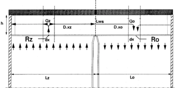
Figure 8.5 – Model for calculating the sound transmission via the plenum above a suspended ceiling (cross-section).
Figure 8.6 –Standardised air-borne sound insulation, Dn;e (=Lp;s – Lp;r + 10log (10/Ar)) via the plenum above a
suspended ceiling of a extruded mineral fibre plate with visible hanging system. a.) standard configuration; b.) above ceiling plate 60 mm mineral woll is added; c.) rock wool (lead) rock wool barrier; d.) combination of b. and c.
The plenum above the suspended ceiling can in fact be considered as a flat air duct which gets its sound from the wall of the duct at the sending side and transmits sound via the wall of the duct on the receiving side. On its way inside the ‘air duct’ from the sending to the receiving side, the sound is subjected to a dampening caused by sound absorption material, i.e. the sound absorbing suspended ceiling. From this description it readily becomes clear that the following are the most relevant parameters:
a. The sound insulation of the suspended ceiling;
Suspended ceilings in offices mostly are modular ceilings. Modular elements of lightweight sound absorbing material are attached to a suspension construction. The sound insulation of such suspended ceilings depends on the mass of the ceiling plates and the seams between plates and suspension construction. A reduction of the sound insulation occurs because of light armatures. b. The sound absorption inside the plenum above the suspended ceiling;
The ceiling plates mostly consist of a hard air-tight layer at their back to improve their sound insulation. This implies that the sound absorption inside the plenum needs to be achieved differently for instance by adding mineral fibre insulation on top of the ceiling plates.
If the sound insulation of the suspended ceiling is too limited, an additional sound barrier is required. Such a barrier can be placed in the plenum above the suspended ceiling right on top of the partition wall. Solutions that have proven in practice are for instance screens made of high density mineral fibre boards and lead of rubber foils (Figure 8.7).
The sound transmission via the plenum below a raised floor is identical to that via the plenum above a suspended ceiling. NEN-ISO 140-9 (1994) presents the details of how this sound transmission via a plenum can be characterised using the standardised air-borne sound insulation Dn;c
; ; ; 10log10 n e p s p r r D L L A = − + (8.17).
The standard prescribes that the sound transmission test chambers should be 4.5 m wide and that the sound transmission only occurs via the suspended ceiling and the plenum above (or the raised floor and the plenum below). If Dn;c is known, the entire sound transmission from one room to the other and the
resulting air-borne sound insulation can be determined in agreement with equation (8.13) as
;/10 /10 10 10log d10Rd 10Dn e res d d S R S S − − = + (8.18).
8.5
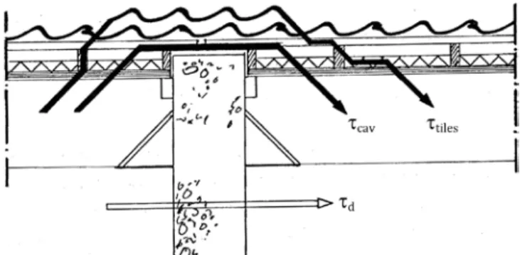
Roofs with tiles
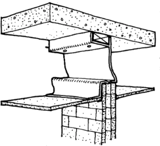
Figure 8.8 shows a typical cross-section of a lightweight construction with roof tiles and its connection to a masonry wall. The thermally insulated roof plates do not continue over the construction wall. Because the lightweight roof construction with a mass of approximately 15 kg/m2 attaches to a heavy construction wall
the vibration reduction index K13 will be high. Due to the tile laths and the roof tiles, however, both roof
boarding surfaces are connected to each other as a result of which with respect to the vibration reduction index the situation of Figure 7.2 is in place. This implies a vibration reduction index which is significantly smaller (around 20 dB smaller). A third transmission path arises from the air cavity below the tiles. Owing to all these flanking transmission paths the air-borne sound insulation index, Ilu, of the separation wall
reduces from about +1 or +2 dB to about -5 dB. Without additional measures to reduce the impact of these flanking paths it is not allowed to position rooms in which people stay, like bed rooms, alongside this construction wall.
The measures that should be taken are:
a. Add a barrier of mineral fibre insulation above the separation wall. This is particularly important when the sound transmission via the cavity between roof boarding and tiles is dominant.
b. Increase the mass of the roof boarding. Per doubling of mass the air-borne sound insulation of this boarding will practically increase with about 5 dB.
c. Add sound absorption material in the cavity of the roof. The sound transmission via the cavity is reduced because the sound pressure level inside the cavity will be reduced because of the added absorption. The sound transmission via the roof tiles will however hardly be affected this way.
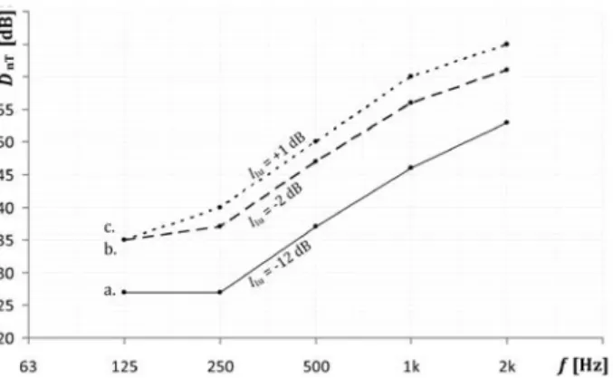
Figure 8.9 – Standardised sound insulation of a roof with tiles connected to a perfect partition wall between two dwellings. a.) base construction with m = 12 kg/m2; b.) base construction with an additional barrier of mineral fibre
insulation; c.) type b.) with heavier roof boarding plates (20 kg/m2).
Figure 8.9 presents the results of measurements of the standardised sound insulation of a roof with tiles and connected to a perfect partition wall for three distinct cases: a base construction with simple roof boarding (flax straw/wood chipboard with PU or PS foam insulation) with a mass of 12 kg/m2; a base
construction with an additional barrier of mineral fibre board; and construction b with heavier roof boarding (20 kg/m2). The discontinuing of the tile laths by an intermediary of mineral fibre is always
necessary. The flanking transmission via the roof tiles themselves in practice limits the achievable Ilu-value
to about 0 to +5 dB at most. This transmission can solely be limited by replacing the regular tiles immediately above the partition wall with soft leaden tiles. This measure does not affect the sound transmission via the cavity between tiles and boarding.
In stead of measures that involve changing the roof construction, measures on the inside of the house can be taken as well: the attachment of a ceiling of soft gypsum board to the lower side of the roof beams. This improves the indirect and flanking sound insulation and at the same time creates an internal finishing.
8.6
Literature
NEN-ISO 140-9 (1994), “Acoustics - Measurement of sound insulation in buildings and building elements - Part 9: Laboratory mesurement of room-to-room airborne sound insulation of a suspended ceiling with a plenum above it”, Nederlands Normalisatie Instituut, Delft.
NEN-EN 12354-1 (2000), “Building acoustics - Estimation of acoustic performance of buildings from the performance of elements - Part 1: Airborne sound insulation between rooms”, Nederlands Normalisatie Instituut, Delft.