EMPOWERING TREATMENT OF
METALLURGICAL WASTEWATERS:
LINKING ELECTROCHEMICAL CELLS
AND SULFUR TREATMENT.
Number of words: 21 515
Michaël De Jonghe
Student number: 01304916Promotor: Prof. dr. ir. Korneel Rabaey
Tutor: Ir. Pieter Ostermeyer
Master’s Dissertation submitted to Ghent University in partial fulfilment of the requirements for the degree of Master of Science in Biochemical Engineering Technology.
Copyright
De auteur en de promotor geven de toelating deze scriptie voor consultatie beschikbaar te stellen en delen van de scriptie te kopiëren voor persoonlijk gebruik. Elk ander gebruik valt onder de beperkingen van het auteursrecht, in het bijzonder met betrekking tot de verplichting de bron uitdrukkelijk te vermelden bij het aanhalen van resultaten uit deze scriptie.
The author and the promotor give the permission to use this thesis for consultation and to copy parts of it for personal use. Every other use is subject to the copyright laws, more specifically the source must be extensively specified when using the results from this thesis.
Ghent, August 21st, 2020
The promotor:
Prof. dr. ir. Korneel Rabaey
The tutor:
Ir. Pieter Ostermeyer
The author:
Acknowledgements
The making of this thesis was a long and intensive road with a lot of setbacks, but it is finally finished. Therefore, I would like to thank several people for their academical, practical and mental support throughout this eventful year. At first, I would like to thank my promotor, Korneel Rabaey, for the opportunity, the constructive input, and the general guidance to the completion of my thesis. Secondly, I would like to thank the following scientists at CMET for their practical help, guidance and assistance through the year: Lotte Van Peteghem, Florian Verbruggen, Antonin Prévoteau and Eleftheria Ntagia.
My eternal gratitude goes to my tutor, Pieter Ostermeyer. Despite your busy schedule you always made time to help, support and check on me. Your teaching really helped me understand better what I was doing at several occasions. I would also like to thank you for the vast explanation and tour of the water treatment plant and the general operation at the precious metal refining company. I’ve learned a lot about bioreactors, reactor building, working in anoxic circumstances, working with gasses, handling dangerous or toxic products and about general metallurgy. You supported me not only on an academical and practical level but also on a mental level which was sometimes necessary after a series of setbacks. Dealing with setbacks is definitely something I will have to keep working on in the future.
Furthermore, I would like to thank my fellow thesis students for their support during the sometimes heavy and long days in the lab. The lunch breaks, hydration breaks and the ‘I will finish this later’ breaks really kept me going and brought some much-needed break from the work.
Finally, I would like to thank my parents not only for their financial support but also because they never stopped believing in me and kept supporting me. To my brother and my friends, thank you for the much-needed relaxation time.
My deepest gratitude! Michaël De Jonghe
Preamble
The outbreak of the COVID-19 virus in Belgium had some adverse effects on the completion of this study. The University of Ghent declared an end on all laboratory activities whilst the Belgian government issued a declaration that everybody was to remain at home during the lockdown. At that time the practical work was in the last testing stage. On the first day of the lockdown, the experiments for the acid sulfide stripping and electrochemical sulfate recovery would have started, giving meaningful and repetitive data. Unfortunately, these experiments were not performed, and the testing data had to be used to determine the results. The conditions in all three tests were different since each test demonstrated its own problems. In the last test (5/03) all practical problems in the set-up were solved.
Unfortunately, while the data of the three tests were being analyzed, an abnormality was observed in all IC results. Since the laboratories were closed, the specific origin of the abnormalities in the measurements could not be determined only hypothesized.
The experimental set-up for electrochemical acid stripping was never built up and no testing could be performed.
After all this negative news, the towel was not thrown in. Since both the electrochemical set-ups did not deliver any results, the processes were theoretically simulated and discussed. All experimental data that was available and meaningful, was used in these theoretical simulations. The operational costs for both systems were calculated based on experimental and theoretical data.
To conclude, this study would have been a lot different if the COVID-19 pandemic had not interfered. More tested data could have been presented and compared with the theoretical simulations that were performed. Deviations of the theoretical data by practical complications could be taken into account to determine a more specific operational cost for both the systems. This all would have leaded to a scientifically more substantiated work.
This preamble was drawn up after consultation between the student and the supervisor and is approved by both.
Abstract
Metallurgical wastewater is nowadays treated with chemical precipitation methods like limestone addition. This non-selective precipitation results in disposal of the sludge impacting the environment. Through biological sulfate reduction, the sulfate in the wastewater can be reduced to sulfides. The produced sulfide rich wastewater can be used to precipitate the metals selectively as metal sulfides at a specific pH. In this study two sulfide stripping techniques are theoretically simulated to remove the dissolved sulfide (DS) as H2S(g). A secondary objective is to test the precipitation of copper from a metallurgical wastewater to copper sulfide.
Sulfide stripping with sulfuric acid is capable to reduce the DS by 56,5 % while removing 552 mg L-1 Cu, 95 mg L-1 As and 324,5 mg L-1 Se from metallurgical wastewater. To make the stripping successful, the pH had to be lowered to 6,5 by addition of sulfuric acid to the sulfide rich wastewater in a ratio of 1,54:1. The stripped medium is post treated by electro-electrodialysis (EED) to recover 70 % or 95% of the total sulfate. The total energy requirement of the system is about 46,3 - 50,5 kWh kg-1 S.
The second method is an electrochemical acid stripping of the sulfides, resulting in a theoretical removal of 75 %. The simulated energy requirement is estimated at 0,5 kWh kg-1 S, making it one of the most efficient and cost-saving methods.
Metallurgical wastewater – electrochemistry – sulfide removal – wastewater treatment – metal precipitation
Samenvatting
Metallurgisch afvalwater wordt hedendaags behandeld met methoden gebaseerd op chemische precipitatie, zoals de toevoeging van kalksteen. Deze niet selectieve precipitatie resulteert in afzetting van het slib, wat een nefast gevolg voor het milieu zal hebben. Door biologische sulfaatreductie kan de sulfaat in het afvalwater gereduceerd worden naar sulfide. Het geproduceerde sulfiderijk afvalwater kan gebruikt worden om de aanwezige metalen selectief te precipiteren als metaalsulfides bij een specifieke pH. In deze thesis worden twee strippingstechnieken theoretisch gesimuleerd om opgeloste sulfides (OS) te verwijderen als H2S(g). Een tweede doelstelling is om de precipitatie van koper naar kopersulfide te testen in het metallurgische afvalwater.
De eerste methode is een sulfide stripping met zwavelzuur en is in staat om de OS te reduceren met 56,5 % terwijl er daarbij 552 mg L-1 Cu, 95 mg L-1 As en 324,5 mg L-1 Se verwijderd wordt uit het metallurgisch afvalwater. Voor een succesvolle stripping moest de pH verlaagd worden tot 6,5 door toevoeging van zwavelzuur in een ratio van 1,54:1 aan het sulfiderijke medium. Het gestripte medium wordt vervolgens behandeld door electro-electrodialyse (EED) om 70 % of 95 % van de totale sulfaat te herwinnen. De totale energievraag van het systeem is tussen de 46,3 - 50,5 kWh kg-1 S.
De tweede methode is een elektrochemische zuurstripping van sulfide dat een theoretische verwijdering van 75 % teweeg brengt. De gesimuleerde energievraag is geschat op 0,5 kWh kg-1 S waardoor het één van de meest efficiënte en kost besparende methodes is.
Metallurgisch afvalwater – elektrochemie – sulfideverwijdering – afvalwaterzuivering – metaal precipitatie
Table of contents
Acknowledgements ... I Preamble ... II Abstract ... III Samenvatting ... IV Table of contents ... V List of acronyms and abbreviations ... VIII List of figures ... IX List of tables ... X1 Introduction ... 1
2 Literature review ... 2
2.1 Sulfate and sulfide in wastewaters ... 2
2.1.1 Sulfate rich waste streams ... 2
2.1.2 Sulfide rich waste streams ... 3
2.2 Methods for sulfate removal ... 4
2.2.1 Gypsum and barium precipitation ... 4
2.2.2 Ion exchange ... 4
2.2.3 Membrane filtration ... 5
2.3 Biological sulfate removal ... 5
2.3.1 Industrial sulfate reducing systems ... 7
2.4 Methods for sulfide removal ... 7
2.4.1 Oxidation ... 7
2.4.1.1 Catalytic wet-air oxidation (CWAO) ... 8
2.4.1.2 Incineration ... 8
2.4.1.3 Chemical oxidation ... 8
2.4.1.4 Electrochemical oxidation ... 9
2.4.1.5 Biological oxidation ... 9
2.4.2 Precipitation ... 10
2.4.3 Acid stripping and (direct) air stripping ... 10
2.5 Electrochemical sulfide stripping ... 13
2.5.1 Ion exchange membranes (IEM) ... 13
2.6 Opportunities ... 14
3 Materials and methods ... 15
3.1 Stock preparations ... 15
3.1.1 Synthetic medium ... 15
3.1.2 Metallurgical wastewater ... 16
3.1.3 Chemical and analytical products ... 16
3.2 Experimental set-up ... 17
3.2.1 Sulfide acid stripping and electrochemical sulfate recovery ... 17
3.2.2 Electrochemical acid stripping ... 21
3.3 Sulfide acid stripping procedure ... 22
3.3.1 Sampling preparation ... 22
3.3.2 Stripping procedure ... 24
3.3.3 Theoretical calculations ... 25
3.4 Electrochemical sulfate recovery ... 25
3.4.1 Sample preparation ... 25
3.4.2 Electrochemical recovery procedure ... 26
3.4.3 Theoretical approach ... 26
3.5 Electrochemical acid stripping ... 27
3.5.1 Theoretical approach ... 27
3.6 Analytic methods ... 28
3.6.1 Anion and cation analysis ... 28
3.6.2 Gas sample analysis ... 28
3.6.3 Dissolved carbonate and sulfide analysis ... 28
3.6.4 Sulfide analysis through spectrophotometry and IC ... 29
3.6.5 Metallurgical wastewater analysis through ICP-OES ... 29
3.6.6 pH measurement ... 29
4 Results & discussion ... 30
4.1 Gas streams in the sulfide acid stripping ... 30
4.1.1 Gas composition in the stripping bottle ... 30
4.1.2 Gas composition in the precipitation bottle ... 32
4.2 Dissolved ions in the sulfide acid stripping ... 34
4.2.1 Sulfate presence in the stripping bottle ... 34
4.2.2 Dissolved sulfide presence in the stripping and precipitation bottle ... 35
4.3 Precipitation of metal in the metallurgical wastewater ... 37
4.3.1 Precipitation of copper ... 37
4.3.2 Precipitation of arsenic ... 38
4.3.3 Precipitation/removal of selenium ... 39
4.4 Practical results for the electrochemical sulfate recovery ... 41
4.5 Theoretical simulation of the electrochemical sulfate recovery ... 42
4.6 Theoretical simulation of the electrochemical acid stripping ... 45
4.7 Theoretical operating expenditures (OPEX) ... 46
5 Conclusion ... 48
6 Future research ... 49
List of acronyms and abbreviations
A Acceptor solutionAD Anaerobic digestion
AEM Anion exchange membrane AMD Acid mine drainage
ATEX Explosive atmospheres CEM Cation exchange membrane cGC Compact gas chromatograph CSTR Continuous stirred-tank reactor CWAO Catalytic wet-air oxidation D Donor solution
DS Dissolved sulfide
DSA Dimensionally stabile anode ED Electrodialysis
EDR Electrodialysis reversal EED Electro-electrodialysis FBR Fluidized bed reactor GLR Gas lift reactor IC Ion chromatography
ICP-OES Inductively coupled plasma optical emission spectrometry IEM Ion exchange membrane
ISED Ion substitution electrodialysis MBR Membrane bioreactor
NC Nanocolor®
OPEX Operational expenditures PBR Packed bed reactor RO Reverse osmosis
SAOB Sulfide anti-oxidizing buffer SOB Sulfur oxidizing bacteria SRB Sulfate reducing bacteria TCD Thermal conductivity detector TDS Total dissolved sulfide
TS Total sulfide
UASB Up-flow anaerobic sludge blanket reactor UPW Ultrapure water
VLAREM Vlaams Reglement betreffende de Milieuvergunning WAO Wet-air oxidation
List of figures
Figure 1: (left) Henderson – Hasselbach graph for the speciation between H2S and HS- in an aqueous solution in relation to changes in pH. (right) Stripping graph for the sulfide stripping efficiency (H2S(g)/ TS) on different pH and different temperatures for a sulfide pressure of 0,02 atm. ... 12 Figure 2: (left) Outline for an electro-electrodialysis system with a CEM at the cathode side and an AEM at the anode side (Jaroszek and Dydo, 2016). (right) Design of combined system of ion substitution electrodialysis and electro-electrodialysis with two CEMs (Jaroszek and Dydo, 2016). ... 14 Figure 3: Schematic design of the sulfide acid stripping with the electrochemical sulfate recovery in transparent. ... 18 Figure 4: Picture taken at the end of a test for the sulfide acid stripping process. The set-up is installed in the fume hood. The ATEX pump is not present in the figure because the pump was installed next to the fume hood. ... 19 Figure 5: Schematic design of the experimental sulfide acid stripping in transparent and electrochemical sulfate recovery. ... 21 Figure 6: Schematic design of the electrochemical acid stripping set-up. ... 22 Figure 7: The volume percentage of H2S(g) (A), CO2 (g) (B), N2 (g) (C)and O2 (g) (D) in the stripping bottle (H1) over time with point -1 equal to H1VA, point 0 equal to H1NA and point 11 equal to H1NS. ... 31 Figure 8: The volume percentage of H2S(g) (A), CO2 (g) (B), N2 (g) (C)and O2 (g) (D) in the precipitation bottle (H2) over time with point 0 equal to H1VA and point 11 equal to H2NS. For H2S only the test of 5/03 is represented in the graph. The test on 27/02 and 28/02 gave no presence of sulfide gas and thus are not shown in the graph. ... 33 Figure 9: The course of the sulfate concentration in the stripping bottle from before acidification (point -1) till after stripping (point 11). ... 35 Figure 10: The evolution of the dissolved sulfide concentration in the stripping bottle. The measurements were performed on the spot with the sulfide Nanocolor® kit. Special xaxis points -1, 0 and 11 represent the sampling point before acidification, after acidification and after stripping. ... 36 Figure 11: The declining concentration of copper due to precipitation with sulfide gas. The higher decrease on 5/03 was induced by the better performance of the third test and the problems encountered in the previous tests, that were solved by 5/03. ... 38 Figure 12: Mild decrease in arsenic concentration because of sulfide precipitation. The higher decrease on 5/03 was induced by the better performance of the third test and the problems encountered in the previous tests, that were solved. ... 39
Figure 13: Decrease in selenium concentration was observed in the ICP-OES results. The decrease can be induced by sulfide precipitation or reduction to elemental selenium by H2S(g) (Geoffroy and Demopoulos, 2011; Pettine et al., 2012). ... 40
List of tables
Table 1: Recommended maximum sulfate levels in mg L-1 (Navigator Wetgeving Leefmilieu Natuur en Energie, 1995; Bowell, 2004). ... 2 Table 2: Sulfate removal rate and total dissolved sulfide (TDS) concentration of different reactor types and different electron donors (van Houten, Pol and Lettinga, 1994; van Houten et al., 1996; Nagpal et al., 2000; Annachhatre and Suktrakoolvait, 2001; Vallero, Lettinga and Lens, 2005; Kaksonen et al., 2006; Brahmacharimayum and Ghosh, 2014). ... 6 Table 3: Composition of effluent from a sulfate reduction treatment on pretreated metallurgical wastewater. ... 15 Table 4: Synthetic approach of the effluent from a sulfate reducing process as represented in Table 3. ... 16 Table 5: Metal composition of the metallurgical wastewater used in this study after removal of most of the solid particles. ... 16 Table 6: Different points in time and locations where samples were taken before, during or after the sulfide acid stripping in the stripping bottle (H1) or in the precipitation bottle (H2). With VA (before acidification), NA (after acidification) and NS (after stripping) as the chosen sampling points in time. ... 23 Table 7: Results of sulfate concentration and sodium concentration for the tests of 28/02 and 5/03. The results are obtained from anion and cation IC. However, the results do not comply with expectations. ... 41 Table 8: Theoretical results in g L-1 for electrochemical sulfate recovery of experiment 1. 100 % efficient circumstances are assumed with no contamination and a discharge sulfate concentration of 3 g L-1 is aimed at. ... 43 Table 9: Theoretical results in g L-1 for electrochemical sulfate recovery of experiment 2. 100% efficient circumstances are assumed with no contamination and a discharge sulfate concentration of 0,5 g L-1 is aimed at. ... 43 Table 10: Contamination of the catholyte and anolyte by migration of the ions assuming the conditions of experiment 4 (worst-case scenario and a sulfate discharge concentration of 0,5 g L -1). ... 44 Table 11: The theoretical currents and coulombic efficiencies for experiments 1, 2, 3 and 4 of the electrochemical sulfate recovery. Experiment 1 and 2 assume 100% efficient circumstances with a discharge sulfate concentration of 3 and 0,5 g L-1 respectively. Experiment 3 and 4 assume worst case scenario. Worst case scenario is defined as migration of all anions from the center compartment through the AEM to the anolyte and equimolar cations through the CEM to the catholyte. Experiment 3 aims at a sulfate discharge of 3 g L-1 whilst experiment 4 aims at 0,5 g L-1.
The coulombic efficiency was calculated by dividing the theoretical charge required for sulfate migration by the amount of electrons used in the system. ... 44 Table 12: Theoretical simulation of the electrochemical acid stripping results. The pH is lowered from 8 to 6,5 and DS is lowered. The current is calculated based on the amount of protons produced at the anode. The coulombic efficiency was calculated by dividing the theoretical charge required for the protonation of the dissolved sulfide by the amount of electrons used in the system. ... 46
1 Introduction
Metallurgical wastewater consists of a high concentration of sulfate and different metals. The current practice to reach the discharge limits for metals and sulfate is precipitation by chemical addition. Limestone is the most used practice to precipitate sulfate and metals. The major disadvantages of chemical precipitation are the non-selective precipitation and the high cost for the chemical addition. A collateral effect of the non-selective precipitation is the forced disposal of the sludge, impacting the environment and raising the costs even more. At present, biological sulfate reduction to sulfide is an upcoming technology. The sulfide rich wastewater produced, can be used to precipitate the metals as metal sulfides. The major advantage of metal sulfide precipitation is the selective precipitation at a specific pH. This makes it possible to concentrate different metals and sell them, consequently nullifying the environmental impact of the disposed sludge.
Sulfide rich wastewaters pose a threat to human health and aquatic life (Strom and Jenkins, 1984), therefore the release in the environment can lead to serious pollution of water bodies and even mass aquatic death. Dissolved sulfide does not pose a threat for human health, only the degassing as H2S(g) (Snyder et al., 1995). The sulfide cycle is closely related to the sulfate cycle since sulfides oxidize spontaneously to sulfate in aerobic conditions. Sulfide rich wastewaters are found in the tanneries, the petrochemical industry and as an effluent from a biological sulfate reduction (Rinzema and Lettinga, 1988; Kuenen and Robertson, 1992; Brimblecombe, 2003).
The scope of this study is the removal of dissolved sulfides as H2S(g) by two methods based on electrodialysis. The sulfide gas will then be used to precipitate copper from a metallurgical wastewater. The first method is an acid stripping with sulfuric acid addition followed by a sulfate recovery by electro-electrodialysis (EED). The second method is an electrochemical acid stripping based on a combination of electro-electrodialysis and ion substitution electrodialysis (ISED).
2 Literature review
2.1 Sulfate and sulfide in wastewaters
2.1.1 Sulfate rich waste streams
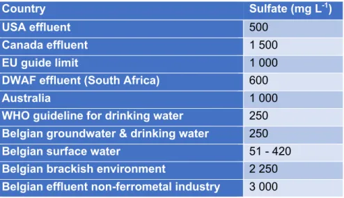
Wastewater from metallurgical industries contains up to multiple grams of sulfate per liter. It is necessary to remove sulfate prior to discharge as guidelines restrict sulfate concentrations in drinking water, groundwater, rivers and brackish water. Vlaams Reglement betreffende de Milieuvergunning (VLAREM) limits sulfate concentration for groundwater and drinking water up to 250 mg L-1, for small rivers up to 90 mg L-1 and for big rivers 150 mg L-1. As seen in Table 1 the World Health Organisation (WHO) guideline for drinking water is 250 mg L-1. Due to the geographical differences (e.g. salinity concentrations in the soil and the size of the stream) in the environment, sulfate concentration limits in Belgium (Table 1) for surface water vary from 51 mg L -1 to 420 mg L-1 (Navigator Wetgeving Leefmilieu Natuur en Energie, 1995). In brackish environment the maximum value is set at 2 250 mg L-1. The cooperating company for this study is classified in the non-ferrometal industry, for which a sulfate limit of 3 000 mg L-1 is defined. In the USA and South Africa (Table 1) a maximum of 500 – 600 mg L-1 is maintained because at levels above 600 mg L-1 human health is impacted (World Health Organization, 1993).
Table 1: Recommended maximum sulfate levels in mg L-1 (Navigator Wetgeving Leefmilieu Natuur en Energie, 1995;
Bowell, 2004).
Country Sulfate (mg L-1)
USA effluent 500
Canada effluent 1 500
EU guide limit 1 000
DWAF effluent (South Africa) 600
Australia 1 000
WHO guideline for drinking water 250 Belgian groundwater & drinking water 250
Belgian surface water 51 - 420
Belgian brackish environment 2 250 Belgian effluent non-ferrometal industry 3 000
Low concentrations of sulfate do not have a direct environmental effect; sulfate is a non-volatile, chemically inert and non-toxic compound. At high concentrations however, the natural sulfur cycle can be unbalanced (Lens et al., 1998; Silva et al., 2002; Zhao et al., 2017). Sulfate concentrations above 600 mg L-1 in drinking water result in diarrhea in mammals (World Health Organization, 1993; Darbi et al., 2003). In anaerobic conditions and in the presence of an electron donor, sulfate can be reduced to sulfides resulting in toxic H2S gas (Ghigliazza, Lodi and Rovatti, 2000).
The main reason of sulfate presence in wastewater in the industrial processes is the use of sulfuric acid in chemical processes. Sulfur compounds are also present in wastewaters used in the pulp and paper industry, the food processing industry, the metallurgical industry and the photographic sector (Pannell and Lu Valle, 1953; Rintala, Sanz Martin and Lettinga, 1991; Konieczny et al., 2005; Weijma et al., 2013). Municipal wastewater typically contains less sulfate, at concentrations of 20 – 500 mg L-1 (Lens et al., 1998).
The sulfide rich wastewater used in this study is the result of a biological sulfate reduction process (see section 2.3) on the sulfate rich wastewater from an international precious metal refinery company. At the company, a smelter is operated to separate precious from non-precious metals. The smelter process is a pyrometallurgical process in which oxygen enriched air is used to oxidize sulfide minerals. As a consequence, the sulfides that are present in the minerals will oxidize to sulfur dioxide (SO2). Among other produced gases (e.g. metal containing gases), the SO2 leaves the smelter as an off gas (10 – 20% w/w). The smelter off gasses are washed with water and are sent to the wastewater treatment plant (Schlesinger et al., 2011; Ge et al., 2018).
2.1.2 Sulfide rich waste streams
Sulfate is present in municipal wastewater systems at low concentrations (Lens et al., 1998) and primarily stems from household cleaning detergents. Anaerobic bacteria in the sewers can reduce sulfate to sulfide, resulting in sulfide rich wastewater (Mahmood et al., 2007). Sulfide rich waste streams are also found in the petrochemical industry, in tanneries, in viscose rayon manufacturing, in the gasification of coal for the generation of electricity, the liquefaction of coal and in the anaerobic treatment of sulfate rich wastewater (Rinzema and Lettinga, 1988; Kuenen and Robertson, 1992; Brimblecombe, 2003; Wang et al., 2009).
The sulfide rich waste stream in this study originates from an anaerobic, biological sulfate reducing process operated on a sulfate rich wastewater (see section 2.1.1). Some industrial systems using this technology are the SULFATEQTM and THIOTEQTM Metal technology from PAQUES N.V. (PAQUES N.V., 2020a, 2020b) which will be discussed a bit more in section 2.3.1.
Spent caustic streams also contain high concentration of sulfides, originating for example from sulfide scrubbers. Caustic scrubbing is a technology that has been used for the removal of H2S from gases in different industries. Improvements in design and control strategies, more favorable prices for caustic compared with other non-regenerating H2S scavenging chemicals and the potential of selling the NaHS product, have made caustic scrubbing an economic and viable option for some refinery streams. The amount of scrubbing of H2S gas in industry can vary between less than 0,1 ton d-1 till more than 15 ton d-1 (Mamrosh, McIntush and Fisher, 2014).
In the anaerobic digestion (AD) of organic wastes (e.g. activated or primary sludge used in wastewater treatment plants or animal manure) sulfuric acid is commonly used to adjust the pH during biological or chemical processing. As a result from the presence of sulfates, sulfides are
generated in the AD by sulfate reducing bacteria in anaerobic respiration (Mahmood et al., 2007). For the handling or treatment of sulfide rich streams special attention is needed for the production of toxic sulfide gas. When H2S(g) is inhaled, the enzyme cytochrome oxidase is inhibited which is an important factor in mitochondrial respiration. At levels of 50 – 100 ppm eye irritation can occur. Even higher levels of 300 – 500 ppm result in severe poisoning which can lead to unconsciousness or even death. H2S presence can easily be detected because of its very low odor threshold (around 0,5 ppb). However, when the human olfactory system is affected and saturated, the toxic gas cannot be smelled anymore (Snyder et al., 1995; Firer, Friedler and Lahav, 2008). In the Belgian royal decree of march 9th 2014 on chemical agents on the job, a long term limit of 5 ppm and a limit of 10 ppm for 15 minutes is described (Federale overheidsdienst werkgelegenheid arbeid en sociaal overleg, 2014). Dissolved sulfide (DS) can affect biological processes in wastewater treatment (e.g. bulking problems and inhibition of anaerobic digestion) (Strom and Jenkins, 1984) and is toxic to fish. A concentration of 0,002 mg L-1 is advised for dissolved sulfides to have no effect on aquatic life (Smith et al., 1976).
2.2 Methods for sulfate removal
Beside biological sulfate removal for the formation of sulfide (see section 2.3), several other methods are known to remove sulfate and will be briefly discussed. For dissolved sulfate removal reverse osmosis, nanofiltration and electrodialysis can be used. These treatments however do not remove other impurities and a post treatment is sometimes necessary (Lens et al., 1998). Two other common methods are ion exchange and precipitation of the sulfate as a sulfate salt.
2.2.1 Gypsum and barium precipitation
There are different methods of chemical precipitation of sulfate. They are based on the fact that sulfate will form a salt that is more insoluble (lower solubility) in aqueous liquid. Both lime and barium salts are most proposed. The most known sulfate precipitation is the addition of lime or limestone to the sulfate containing solution forming gypsum or calcium sulfate dihydrate (Gominšek, Lubej and Pohar, 2005). The removal of sulfate by addition of BaCO3 was developed about 50 years ago (Kun, 1972). There were however several problems with the technique on an industrial scale: the requirement of more barium in solution than is calculated stoichiometrically, long retention times and the high cost of barium. Moreover barium is a toxic compound and barium containing waste requires disposal which will increase cost and the environmental impact (Lens et al., 1998; Ghigliazza, Lodi and Rovatti, 2000).
2.2.2 Ion exchange
Ion exchange resins are materials which contain large polar exchange groups held together by a three dimensional network (Helfferich, 1995). For the removal of sulfate, anion exchange columns can be used (Darbi et al., 2003). One of the targeted ions is removed from the liquid phase and captured by the solid resin structure in exchange for another ion (typically hydroxyl). In an anion
exchange column, the maximum removal of sulfate anions takes place at a resin dosage of 1000 mg/ 100 mL. The adsorption of sulfate anions on the resin follows reversible first-order kinetics (Haghsheno et al., 2009). The GYPCIX process is a specialized ion exchange that can treat sulfate levels up to 2 g L-1 (Robertson, Everett and Du Plessis, 1994).
2.2.3 Membrane filtration
Nanofiltration is one of the most frequently used method for separation of suspended particles from fluids (Buchanan, 1987). It is a pressure-driven membrane filtration that is categorized between reverse osmosis and ultrafiltration if pore size is compared. Because of its advantages, such as low operation pressure, high permeate flux, high retention of multivalent anions, relatively low investment, low operation and maintenance cost and environmental friendliness, it has given rise to worldwide interest and has been used in different separation applications (Meihong et al., 2008). Reverse osmosis (RO) is a separation technique that uses a semi-permeable membrane to part a strong solution and a dilute solution. The hydraulic force is called the osmotic pressure of the system. In reverse osmosis an external hydraulic force is applied on the sulfate rich water, conquering the osmotic pressure and forcing the water to permeate to the diluted side of the membrane. Sulfate concentrations up to 700 mg L-1 can be separated with conventional RO (Darbi et al., 2003).
Electrodialysis (ED) and electrodialysis reversal (EDR) uses a direct electrical current across a stack of alternating cation and anion selective membranes. Anions such as sulfates are attracted to the anode and concentrated in the anolyte. Inversely, cations are concentrated in the catholyte. The initial solution can be depleted of salts and the cleaned water can be discharged. By the use of current reversal (EDR), the anode and cathode can be periodically changed as can the effluent and clean water channels. This reduces membrane fouling and facilitates regeneration of the membrane by self-cleaning. A major advantage of EDR over other RO techniques is that the system is not sensitive to effluent temperature or pH. Capital and operational costs are reduced due to lower working pressures. (Juby and Pulles, 1990; Hanrahan et al., 2015).
2.3 Biological sulfate removal
In this thesis there is a focus on biological sulfate removal initiating the electrochemical post treatment of the sulfides. The biological sulfate removal technology is based on the metabolism of sulfate reducing bacteria (SRB).
SRB can be heterotrophic (using an organic electron donor) or autotrophic (using an inorganic electron donor and a carbon source) anaerobes, reducing sulfate through a dissimilatory, bioenergetic metabolism (Nagpal et al., 2000). SRB are present in most water or soil because of their ability to utilize a wide variety of substrates. Moreover SRB are resistant to extreme conditions (Schwartz, 1985). To function optimally, SRB need specific conditions such as an anaerobic environment, pH higher than 5, the presence of an electron donor and the presence of a pertinent
sulfur source like sulfate to be reduced (Gibert et al., 2002). Biological sulfate reduction can be operated at mesophilic (25 – 35 °C) or at thermophilic conditions (35 – 70 °C). Thermophilic conditions are preferred if the sulfate rich wastewater is at high temperature such as wastewater from the pulp and paper industry, rayon manufacturing process and flue gas desulfurization (Shreve and Austin, 1984).
Metallurgical wastewaters are deficient in electron donors. SRB can use different electron donors of which the most commonly used are hydrogen, methanol, ethanol, acetate, lactate, propionate, butyrate, sugar and molasses (Liamleam and Annachhatre, 2007). Biomass production is one of the criteria to choose the electron donor for the wanted application. Some applications are based on large biomass production while other systems require low biomass production (Speece, 1983). The most performant electron donors used for sulfate reduction are H2/CO2, acetate and ethanol removing respectively 30 g L-1 day-1, 28 g L-1 day-1 and 21 g L-1 day-1 (van Houten, Pol and Lettinga, 1994; Smul et al., 1997; De Smul and Verstraete, 1999).
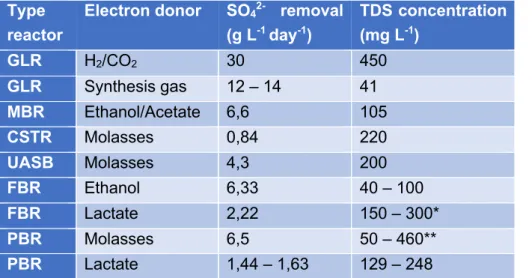
Several reactor systems are available for biological sulfate reduction, the most current types of bioreactors used are the packed bed reactor (PBR), the continuous stirred-tank reactor (CSTR), the gas lift reactor (GLR), the fluidized bed reactor (FBR), the membrane reactor (MBR) and the up flow anaerobic sludge blanket reactor (UASB). The sulfide rich stream used in this study was based on experimental data of the effluent of a PBR system using H2 as the energy source and HCO3- as the carbon source. For all the types of reactors, some sulfate removal results and total dissolved sulfide (TDS) concentration of the effluent are briefly described in Table 2.
Table 2: Sulfate removal rate and total dissolved sulfide (TDS) concentration of different reactor types and different electron donors (van Houten, Pol and Lettinga, 1994; van Houten et al., 1996; Nagpal et al., 2000; Annachhatre and Suktrakoolvait, 2001; Vallero, Lettinga and Lens, 2005; Kaksonen et al., 2006; Brahmacharimayum and Ghosh, 2014).
Type reactor
Electron donor SO42- removal
(g L-1 day-1) TDS concentration (mg L-1) GLR H2/CO2 30 450 GLR Synthesis gas 12 – 14 41 MBR Ethanol/Acetate 6,6 105 CSTR Molasses 0,84 220 UASB Molasses 4,3 200 FBR Ethanol 6,33 40 – 100 FBR Lactate 2,22 150 – 300* PBR Molasses 6,5 50 – 460** PBR Lactate 1,44 – 1,63 129 – 248
*Zinc and iron were present in the FBR for precipitation with the sulfides. **Different metals were present in the reactor and sulfide concentration was not accurately measured.
2.3.1 Industrial sulfate reducing systems
The SULFATEQTM process is developed by the PAQUES company (Netherlands) (Van Lier, Buisman and Piret, 1999). Sulfide is produced by bringing a sulfate rich stream into contact with SRB in the presence of an electron donor like H2 or acetate. Sulfides in this system are used to precipitate different metals, the excess sulfides are converted into elemental sulfur in a post-treatment process, namely a biological or abiotic oxidation (Van Lier, Buisman and Piret, 1999; Reinsel, 2015; PAQUES N.V., 2020a).
Some of the advantages of this system are (Reinsel, 2015):
1) Most of the present H2S is present in the dissolved phase and not in the gas phase by pH regulation (pH 8 – 9).
2) The process operates at ambient temperatures. 3) Variation in the flow rates is possible.
The THIOTEQTM Metal technology is a similar technology developed by PAQUES that is aimed at the removal of higher metal concentrations up to 5 g L-1. Elemental sulfur is reduced in a bioreactor in the presence of an electron donor like H2 or an organic compound. The produced sulfide gas is subsequently bubbled into a contactor vessel containing the metal solution. In the contactor vessel the metals are precipitated to metal sulfides. By controlling the pH, metal sulfides can be recovered selectively. The process is split in 2 vessels: the sulfur reducing bioreactor and the contactor vessel, while the SULFATEQTM system operates a simultaneous sulfate removal and metal precipitation in 1 vessel (PAQUES N.V., 2020b). In comparison to hydroxide precipitation, the system delivers an effluent with lower metal concentrations and the metal sulfide can be sold afterwards for profit. An advantage for both systems is the biogenic on-site sulfide production under ambient conditions which completely nullifies the costs of transport, storage or production of NaHS or H2S in a chemical way (PAQUES N.V., 2020b).
2.4 Methods for sulfide removal
Several physicochemical methods such as (direct) air stripping, acid stripping, oxidation and precipitation are used for sulfide removal (Altaş and Büyükgüngör, 2008; Midha and Dey, 2008).
2.4.1 Oxidation
There are several oxidation processes: catalytic wet-air, incineration, electrochemical, biological, bio-electrochemical and chemical oxidation (Chen and Morris, 1972; Paskall and Ritter, 1981; Buisman et al., 1990; Alnaizy, 2008; Dong et al., 2017). Several examples of chemical oxidation processes are aeration (catalyzed or uncatalyzed), ozonation, chlorination, potassium permanganate treatment and hydrogen peroxide treatment (Dell’Orco et al., 1998; Zhang and Tong, 2006; Midha and Dey, 2008). For the system operated in this study, a major drawback for most oxidation technologies is the possibility on oxidation to sulfite, thiosulfate or sulfate, which
nullifies the previous reduction of sulfate to sulfide by the SRB (see section 2.3). Only the oxidation techniques with a very high efficiency to oxidize the sulfides to sulfur could prove economically interesting.
2.4.1.1 Catalytic wet-air oxidation (CWAO)
Thermal liquid-phase or wet-air oxidation (WAO) is a process used for the abatement of toxic and hazardous organic compounds in liquid waste streams. The aqueous flameless combustion process in which active oxygen species are generated (e.g. hydroxyl radicals), occurs at high reaction temperatures ranging from 175 to 295 °C and pressures of 20 to 200 bar. The treatment is mostly used for removal of organic compounds but can also oxidize sulfide to the more innocuous sulfur and/or sulfate (Jung et al., 2003). The oxidation efficiency of WAO can be considerably improved by the use of solid or homogenous catalysts. CWAO has lower energy demand than WAO and consequently can operate at much lower reaction temperatures and lower pressures (Levec and Pintar, 2007). An important disadvantage is the possible oxidation of sulfide to the toxic sulfur dioxide. However, elaborate preventive research of the catalysts can prevent the risk on SO2 formation (Jung et al., 2003). The major advantage of the system is the sulfide removal rate higher than 99%. Some of the used catalyst are O2, Fe/Cu, Fe/MgO (Jung et al., 2003; Zhang and Tong, 2006; Hafif Bin Jalil et al., 2018).
2.4.1.2 Incineration
Sulfur plant tail gas incinerators are used to oxidize sulfide compounds like H2S, COS and CS2. Incinerators are operated at temperatures (149 – 482 °C) that are capable to oxidize the sulfur compounds to SO2 as well as providing a required mechanism for proper fume dispersion (Hass, Hansford and Hennig, 1978; Paskall and Ritter, 1981). Sulfur dioxide, a gaseous pollutant in the atmosphere, is an unwanted end product (Demirbas, 2004). This can be solved by using the gaseous SO2 to produce dilute sulfuric acid. Mixtures of SO2 and O2 are bubbled through water to oxidize the SO2 to sulfuric acid, a catalyst can be added such as MnSO4 to optimize the reaction (Copson and Payne, 1933).
2.4.1.3 Chemical oxidation
Chemical oxidation of sulfide rich wastewater is also possible in multiple ways. One such method is aeration (catalyzed or uncatalyzed). Uncatalyzed aeration of sulfide containing streams is a very slow process; the oxidation rate will be 12 mg L-1 h-1 at an oxygen concentration of 3 mg L-1 and sulfide levels of 12 mg L-1 (Jolley and Forster, 1985). Catalyzed aeration of sulfide with air achieves an oxidation rate of 116 mg L-1 when KMnO
4 was used as a catalyst (Martin and Rubin, 1978). Activated carbon as a catalyst at a concentration of 53 or 530 mg L-1, results in oxidation rates of 237 or 752 mg L-1 (Lefers, Koetsier and Van Swaaij, 1978).
Chlorination (see Eq. 1) is a less interesting technique because of the formation of undesirable chlorinated products when organic compounds are present (Cadena and Peters, 1988).
𝐻!𝑆 + 𝑂𝐶𝑙" → 𝑆# + 𝐻
!𝑂 + 𝐶𝑙" (𝑝𝐻 < 7,5) Eq. 1
Ozonation is the most expensive method for sulfide oxidation. Potassium permanganate (see Eq. 2) is also a not very attractive method primarily because of the high cost and secondly because of the manganese dioxide sludge generated that has to be disposed at the end (Butler and Nandan, 1981).
3 𝐻!𝑆 + 4 𝐾𝑀𝑛𝑂$ → 2 𝐾!𝑆𝑂$+ 𝑆#+ 3 𝑀𝑛𝑂 + 𝑀𝑛𝑂!+ 3 𝐻!𝑂 (𝑝𝐻 < 7,5) Eq. 2
The use of hydrogen peroxide oxidizes the hydrogen sulfide to elemental sulfur (see Eq. 3): 𝐻!𝑆 + 𝐻!𝑂! → 𝑆# + 2 𝐻!𝑂 (𝑝𝐻 < 7,5) Eq. 3
In all these processes sulfite, sulfate and thiosulfate are generated, which are difficult to separate (Midha and Dey, 2008) and can therefore count as an disadvantage in some circumstances.
2.4.1.4 Electrochemical oxidation
Electrochemical sulfide oxidation can be done indirectly, directly or in a mixed manner. In the case of indirect oxidation, the sulfide is oxidized by intermediate oxidants that are formed in the anodic compartment of a two-chamber electrochemical cell (e.g. OH•, O2, Cl2) (Pikaar, René A. Rozendal, et al., 2011). The final mixture consists out elemental sulfur, polysulfides, sulfate and thiosulfate (Mao et al., 1991; Miller and Chen, 2005; Pikaar, René A Rozendal, et al., 2011). The oxidation products depends on the material of the electrode and the operational conditions (e.g. sulfide concentration, pH, convection and the potential of the anode) (Song et al., 2008; Dutta et al., 2009; Vaiopoulou et al., 2016). For direct oxidation, the elemental sulfur is produced and deposited on the anodic surface (Vaiopoulou et al., 2016).
Electrochemical oxidation is one of the more sustainable ways of oxidizing sulfide into sulfur: Primarily it is a chemical free alternative technique, secondly the sulfide recovery in the form of elemental sulfur and at last the recovery of hydrogen (Rabaey et al., 2006). Some of the disadvantages of the method are fouling of the anode, high-energy input to generate oxidizing agents, the price and high environmental impact of materials and the non-selective oxidation with low efficiency for production of elemental sulfur (< 50%) (Vaiopoulou et al., 2016).
2.4.1.5 Biological oxidation
The biological removal of sulfides is based on the metabolic activities of photoautotrophic or chemolithotrophic sulfur-oxidizing bacteria (SOB). The photoautotrophic SOB will use light as an energy source for their metabolism while the chemolithotrophic SOB receive energy directly from the redox reactions. In some cases of redox reactions, O2 can function as electron acceptor (aerobic microbial species). Nitrates or nitrites can also be used as electron acceptor (anoxic microbial species or denitrifying bacteria), but this is not commonly applied as this implies the
presence or addition of nitrates and nitrites (Tang, Baskaran and Nemati, 2009). Chemolithotrophic SOB are most frequently used for biological oxidation. They are also known as colorless sulfur-oxidizing bacteria and some of the main members are Thiobacillus, Sulfolobus, Thermothrix, Beggiatoa and Thiotrix (Pokorna and Zabranska, 2015). They distinguish themselves from photoautotrophic SOB by a high rate of sulfide oxidation, modest nutritional requirements and an extremely high affinity for sulfides and oxygen. Due to these features, the colorless SOB are excellent alternatives for chemical oxidation in both the natural environment and bioreactors (Janssen et al., 1998).
2.4.2 Precipitation
Sulfide removal by precipitation is a frequently used removal technique that is based on sulfide precipitation as metal sulfides by addition of metals. Iron, both ferrous iron (Fe2+) and ferric iron (Fe3+), is most frequently used. In Eq. 4 the precipitation of ferrous iron and sulfide is given. In contrast to ferrous iron, ferric iron will oxidize the sulfide to elemental sulfur at a pH lower than 7,5 (see Eq. 5), a second reaction (see Eq. 6) between ferric iron and sulfide is the formation of iron(III)sulfide (Nielsen, Hvitved-Jacobsen and Vollertsen, 2008). Eq. 7 shows that Fe2S3 further transforms to produce the more stable Fe3S4 and FeS2 (Davydov, Chuang and Sanger, 1998).
𝐹𝑒!%+ 𝐻𝑆" → 𝐹𝑒𝑆 ↓ +𝐻% Eq. 4
2 𝐹𝑒&%+ 3 𝐻𝑆" → 2 𝐹𝑒𝑆 ↓ + 𝑆# + 3 𝐻% Eq. 5
2 𝐹𝑒&%+ 3 𝐻𝑆" → 𝐹𝑒
!𝑆& ↓ + 3 𝐻% Eq. 6
2 𝐹𝑒!𝑆&(() → 𝐹𝑒&𝑆$(() ↓ + 𝐹𝑒𝑆!(() ↓ Eq. 7
Experiments with a mixture of ferrous iron and ferric iron in a molar ratio of 1:2 proved to have a higher sulfide removal efficiency than that of either salt by itself. Eq. 8 shows a hypothetical reaction to explain the observation (Padival, Kimbell and Redner, 1995). Further experiments showed that a mixture of both iron species was indeed responsible for a better removal efficiency when a molar ratio of 1,33 (Fe) to 1 (S) was maintained (Firer, Friedler and Lahav, 2008).
𝐹𝑒!%+ 2 𝐹𝑒&%+ 4 𝐻𝑆" → 𝐹𝑒
&𝑆$ ↓ + 4 𝐻% Eq. 8
2.4.3 Acid stripping and (direct) air stripping
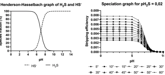
Acid stripping and (direct) air stripping are removal technologies that are based on the degassing of H2S. Important factors in the stripping of H2S are the pH, pKa value which is 6,99 for sulfide, and Henry’s law. Eq. 9 shows the balance of aqueous H2S and dissolved HS-, which is dependent on the pH of the solution. If the pH of the solution is lower than the pKa (6,99), the concentration of H2S(aq) will be higher than the concentration of HS-(aq). In Eq. 10 and Figure 1 (left) the Henderson – Hasselbach equation is described, this equation shows that the concentration of H2S(aq) will
increase with lowering pH and the concentration of HS-(aq) will increase with increasing pH. Figure 1 (left) visualizes the change in pH for a given sulfide solution. Eq. 11 shows the balance between the concentration of sulfide in the gas phase and in the aqueous phase. The chemical balance is dependent on Henry’s law which states that the amount of dissolved gas is proportional to its partial pressure in the gas phase. The proportionality factor is called the Henry’s law constant (Sander, 2015). Henry’s solubility can be defined via concentration (see Eq. 12) with ‘ca’ the concentration of a species in the aqueous phase and ‘p’ the partial pressure of that species in the gas phase at ambient temperature (25 °C). Henry’s solubility constant for H2S equals 0,1 mol (L atm)-1 (Sander, 2015). 𝐻!𝑆(*+) ↔ 𝐻(*+)% + 𝐻𝑆(*+)" Eq. 9 𝐾,!-= [𝐻 %][𝐻𝑆"] [𝐻!𝑆] = Eq. 10 𝐻!𝑆(.) ↔ 𝐻!𝑆(*+) Eq. 11 𝐻/0= 𝑐*? 𝑝 Eq. 12
Figure 1 (right) shows the relation of H2S stripping efficiency to the change in pH at different temperatures. The stripping efficiency is given in Eq. 15 and is the ratio of the concentration of sulfide in the gas phase to the total concentration of sulfide (TS) in the system (see Eq. 14). The temperature dependence of the Henry’s law constant is generally explained with the van ‘t Hoff equation (see Eq. 13). In Eq. 13 H1 and H2 represent the Henry’s law constants at temperature 1 and 2 respectively, -△solH represents the enthalpy of dissolution, where H refers to the enthalpy (Sander, 2015). An increase in temperature will lead to a higher Henry’s law constant, thus a higher stripping efficiency. Figure 1 (right) shows that the efficiency of sulfide will increase with a decrease in pH and at higher temperatures. On these 2 principles (direct) air stripping and acid stripping technologies are based.
𝑙𝑛 (𝐻! 𝐻1 ? ) = −∆(23𝐻 𝑅 ? (1 𝑇? − 1 𝑇! ? ) 1 Eq. 13 𝑇𝑜𝑡𝑎𝑙 𝑠𝑢𝑙𝑓𝑖𝑑𝑒 (𝑇𝑆) = 𝐻!𝑆(.)+ 𝐻!𝑆(*+)+ 𝐻𝑆(*+)" Eq. 14 𝑆𝑡𝑟𝑖𝑝𝑝𝑖𝑛𝑔 𝑒𝑓𝑓𝑖𝑐𝑖𝑒𝑛𝑐𝑦 = 𝐻!𝑆(.)? 𝑇𝑆 Eq. 15
Figure 1: (left) Henderson – Hasselbach graph for the speciation between H2S and HS- in an aqueous solution in
relation to changes in pH. (right) Stripping graph for the sulfide stripping efficiency (H2S(g)/ TS) on different pH and
different temperatures for a sulfide pressure of 0,02 atm.
Acid stripping of sulfides is a sulfide removal technique that uses the addition of an acid, mostly sulfuric acid or hydrochloric acid, to lower pH. Furthermore, a carrier gas is introduced in the system to blow the H2S gas out the system. The stripped H2S is subsequently scrubbed with NaOH or a zinc acetate solution (Wang et al., 2009). The NaHS solution that is produced in the scrubbing process with NaOH can be sold afterwards to make profit.
Sometimes the technique is used without the addition of acid, in this case the term ‘(direct) air stripping’ is preferred. For sulfide air stripping at basic pH, removal rates from 8,9% up to 68% are reported at a gas rate of 60 L h-1 and stripping time ranging from 1 – 12 hours (Wang et al., 2009). Other than stripping, gas rate is an important key actor in sulfide stripping removal. At a stripping duration of 4 hours, a gas rate increase from 30 to 240 L h-1 resulted in an increase of 10 to approximately 80% in removal efficiency. A major drawback of direct air stripping is the voluminous air stream contaminated with sulfide gas at the end of the process that has to be treated (Buisman et al., 1989).
Figure 1 (right) shows that acid stripping of sulfide wastewater is more effective than air stripping because of the higher gas efficiency at lower pH. The wastewater is acidified to convert more aqueous sulfide into gaseous H2S, resulting in an increased removal efficiency reaching up to 99% (Wang et al., 2009).
2.5 Electrochemical sulfide stripping
2.5.1 Ion exchange membranes (IEM)
Although ion exchange membranes are widely used in various industries, the lack of permselectivity for specific ions through the membranes is nowadays still an unsolved problem (Sata, 1994). The most currently used IEMs consist of polymeric resins with attached, charged, functional groups. A distinction is made between anion-exchange membranes (AEM) and cation-exchange membranes (CEM) based on selectivity. AEMs incorporate positively charged functional groups, thus retain the cations and favor the transfer of anions by Donnan exclusion (Strathmann, 2004; Tanaka, 2007). CEMs have negatively charged functional groups, retaining the anions and allowing the cations to pass through the membrane (Jaroszek and Dydo, 2016).
The lower permselectivity of AEMs than CEMs combined with the restrictions arranged by the nature of the used ionic groups (mostly quaternary ammonium) limits the applicability of IEMs when acids are involved. The limited concentration of acid that can be used due to eventual proton leakage is an example of the limits in applicability (Cherif et al., 1988; Tanaka, 2007). The best membranes for acid processes are those in which the absorption of acid and diffusion of protons are minimized (Cherif et al., 1988).
2.5.2 Electro-electrodialysis and ion substitution electrodialysis
Electro-electrodialysis is an electrochemical process that uses IEMs to transfer ions from a center compartment to the anolyte and catholyte (see Figure 2 (left)). In a three-compartment stack, a solution is introduced in the middle compartment from where the anions or cations are transferred through the AEM to the anolyte and through the CEM to the catholyte respectively, depleting the salt solution in the process. The electrolytic processes of water at the anode and cathode contribute to the formation of acid and base respectively (Jaroszek and Dydo, 2016).
The depletion of the salt concentration will increase the voltage, thus increasing the operational cost. The concentration of products is limited by the water transport, the chemical resistance of the IEMs and by the proton leakage. Substantial proton leakage will lead to acidification of the center compartment and will subsequently interfere with the coulombic efficiency. The protons will be favored over the present cations by the CEM and water will be produced in the catholyte (Jörissen and Simmrock, 1991; Rakib et al., 1999).
In ion substitution electrodialysis the IEMs work as the ion exchanger. Instead of switching between CEMs and AEMs, pairs of one type of membrane are used and separated by one opposite IEM. When an electric current is applied ions from the donor solution (D) are exchanged to the adjacent product compartment while ions from the product stream are transported to an acceptor solution (A). In this process the donor solution salinity is reduced and the ions in the product stream are substituted (Kumar, Bijay P Tripathi and Shahi, 2009; Kumar, Bijay P. Tripathi and Shahi, 2009;
Jaroszek and Dydo, 2016). Figure 2 (right) shows the design of an EED combined with an ISED system.
Figure 2: (left) Outline for an electro-electrodialysis system with a CEM at the cathode side and an AEM at the anode side (Jaroszek and Dydo, 2016). (right) Design of combined system of ion substitution electrodialysis and electro-electrodialysis with two CEMs (Jaroszek and Dydo, 2016).
2.6 Opportunities
The two technologies tested in this study to remove sulfide from sulfide rich wastewater are both based on the idea of a zero-chemical approach. No external chemicals need to be consumed in the system for it to be effective. Only electricity is used to operate both systems. Technologies based on oxidation of sulfide would have a negative outcome since this will result in the production of sulfate and other soluble oxidized sulfur compounds which have previously been reduced in a sulfate reducing bioreactor. Only when oxidation of sulfide to only sulfur can be guaranteed, oxidation can be considered.
The second and most interesting advantage of this technology is the sulfide gas that can be used to selectively precipitate the different metals present in metallurgical wastewater by altering the pH. The selectivity for metal precipitation is interesting in both an economical and environmental way. The metals can be separated individually from a mixture, removing the necessity and the cost to dispose of the waste, and gaining the opportunity to sell the different metals.
The technologies described in this study have a high potential for use in the treatment of metallurgical wastewater, bioleachate solution or acid mine drainage (AMD).
3 Materials and methods
3.1 Stock preparations
3.1.1 Synthetic medium
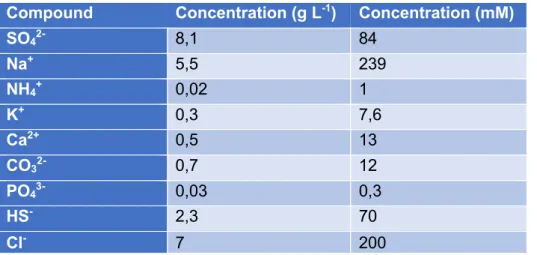
The synthetic medium used for this study is based on the effluent from a sulfate reducing bioreactor. The composition of this effluent can be seen in Table 3. Table 4 shows the compounds used for the preparation of the synthetic bioreactor effluent. The bioreactor was operated at pH 8. Since chlorides were excluded from the synthetic medium for safety reasons, the chloride concentration from the original effluent of the bioreactor was neglected in Table 4.
Table 3: Composition of effluent from a sulfate reduction treatment on pretreated metallurgical wastewater.
Compound Concentration (g L-1) Concentration (mM)
SO42- 8,1 84 Na+ 5,5 239 NH4+ 0,02 1 K+ 0,3 7,6 Ca2+ 0,5 13 CO32- 0,7 12 PO43- 0,03 0,3 HS- 2,3 70 Cl- 7 200
The synthetic medium was prepared in a 5 L volumetric flask. First, 4 L of distilled water was added using volumetric glassware. Next, a total of 58,64 mL of sulfuric acid (50%, Carl Roth) had to be added to the mixture; 2 mL was kept apart for later use and 56,64 mL was added to the distilled water under the fume hood with a volumetric pump. The volumetric flask was placed on a magnetic stirrer (Scilogex MS-H-Pro) out of the hood and the solution was mixed continuously. 4,365 g, 0,46 g and 0,28 g of Ca(OH)2 (95%, Sigma-Aldrich), (NH4)2SO4 (99,5%, Carl Roth), and Na2HPO4.2H2O (99%, Carl Roth) respectively, were weighed using a microbalance (QUINTIX224-1S, Sartorius, Germany) and were added to the solution. When the previous products were dissolved, the pH was measured and approximately 65,1 mL NaOH (32%, Carl Roth) was added carefully with micropipettes of 5 mL and 100 µL until a pH of 7 was reached. In the next step 1,36 g NaHCO3 (99,5%, Carl Roth) and 2,395 g K2CO3 (99%, Carl Roth)were added. At this point the final 2 mL sulfuric acid (50%) was added to lower the pH. 1 mL NaOH (32%) was added slowly to bring the solution to a final pH of 8.
Special care was required to reach the required pH. If the resulting pH was below pH 6,5, carbonates would have started to degas as CO2, while a pH above 8 required the addition of
additional sulfuric acid, resulting in a higher sulfate concentration in the synthetic medium. The NaHS (>90%, Sigma Aldrich) was added at the start of the experiment (see 3.3.2).
Table 4: Synthetic approach of the effluent from a sulfate reducing process as represented in Table 3.
Compound Concentration (g L-1) Compound Concentration (g L-1)
(NH4)2SO4 0,092 NaHCO3 0,272
K2CO3 0,479 Na2HPO4.2H2O 0,056
Ca(OH)2 0,873 NaHS 4,025
H2SO4 8,207 NaOH 5,710*
*This value is an approximation because NaOH was used to change the pH of the solution to the wanted level (pH 8).
3.1.2 Metallurgical wastewater
The metallurgical wastewater used in this study originated from an international precious metal refining plant.
Table 5 shows the concentrations of the different metals present in the wastewater.
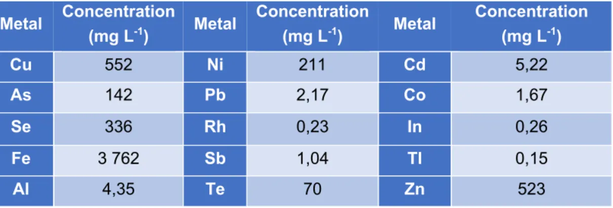
Table 5: Metal composition of the metallurgical wastewater used in this study after removal of most of the solid particles.
Metal Concentration (mg L-1) Metal Concentration (mg L-1) Metal Concentration (mg L-1) Cu 552 Ni 211 Cd 5,22 As 142 Pb 2,17 Co 1,67 Se 336 Rh 0,23 In 0,26 Fe 3 762 Sb 1,04 Tl 0,15 Al 4,35 Te 70 Zn 523
3.1.3 Chemical and analytical products
To run the sulfide acid stripping and electrochemical sulfate recovery, 2 L of 1 M H2SO4 and 1 L of 1 M NaOH were needed to be prepared for every run. The 1 M NaOH solution was prepared in a 1 L Schott bottle (Duran® Original GL45) which was placed on a magnetic stirrer. 1 L of distilled water was measured in a 1 L volumetric flask and poured in the Schott bottle. 40 g NaOH (98%, Carl Roth) was weighed and slowly added to the distilled water to induce optimal mixing and dissolving of the product.
The 1 M H2SO4 solution was prepared in duplicate in two 1 L Schott bottles. Firstly, a 1 L volumetric flask was filled with 250 – 500 mL of distilled water and placed under the fume hood. Secondly, 140 mL of sulfuric acid (50%) was added to the distilled water with a 10 mL micropipette and a 100
µL micropipette for precision. At last, the volumetric flask was filled to a final volume of 1 L and the solution was transferred into the Schott bottle, sealed off and labeled with the necessary stickers. To preserve sulfide samples, a sulfide anti-oxidizing buffer (SAOB) was added to the samples taken for sulfide determination. The SAOB was prepared by dispensing 100 mL of ultrapure water (UPW) in a 100 mL Schott bottle. The UPW was sparged with argon gas for 30 minutes while the Schott bottle and tube were covered with parafilm. In the meantime, 0,32 g NaOH and 0,30 g of ascorbic acid were weighed on the microbalance. The NaOH was added without disrupting the sparging of argon. After 30 minutes ascorbic acid was added, and the Schott bottle was quickly closed off because the solution had to remain as anoxic as possible. The bottle was closed off with a rubber cap and twist lock. In the cap a needle was inserted, the needle was connected to a valve that closed off the environment. To withdraw a certain volume, the bottle was flipped upside down, a syringe was connected to the valve and the valve was opened. The transparent SAOB solution will change color to more brownish overtime by leaks of oxygen. It was therefore important to prepare the SAOB fresh before experiments are were planned and to refresh the SAOB on time. The samples are diluted with de-aerated UPW.
3.2 Experimental set-up
3.2.1 Sulfide acid stripping and electrochemical sulfate recovery
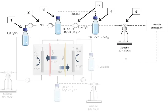
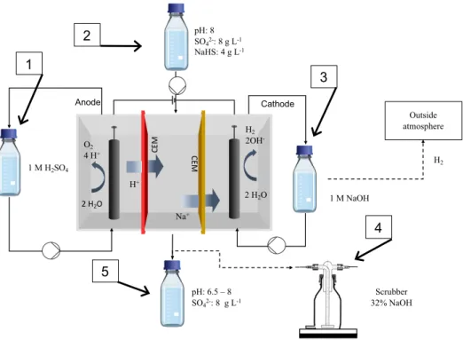
The sulfide rich waste stream is stripped of sulfides by sulfuric acid addition, lowering the pH from 8 to 6,5. As discussed in section 2.4.3, the lower pH ensures a better stripping efficiency. A pH of 6,5 is chosen for the wastewater to be in agreement with the local discharge restrictions. Instead of blowing the sulfide out of the system with a carrier gas. The sulfide gas is bubbled through another vessel containing the original metallurgical wastewater. The second vessel is also connected back to the stripping vessel to ensure a closed gas circulation. In the second vessel some of the metals, mostly copper, will interact with the sulfide gas and precipitate as copper sulfides, removing copper and sulfide from the system. After the stripping process, the concentration of the sulfides in the stripping bottle will be reduced and the concentration of sulfate will be increased by the addition of sulfuric acid.
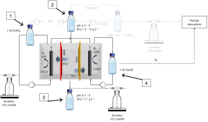
To recover the sulfate, the solution of the stripping bottle is treated by electro-electrodialysis (see Figure 2 left). The sulfate rich solution will pass through the middle compartment of a three-compartment electrochemical cell. Between the anode and the middle three-compartment an AEM is installed ensuring the transfer of sulfate to the anolyte. On the cathode side, a CEM separates the middle compartment and the cathode, ensuring the transfer of sodium to the catholyte. The electrolysis of water at both anode and cathode and the ion exchange will result in formation of sulfuric acid and sodium hydroxide, respectively. The sulfuric acid produced can subsequently be used to acidify the sulfide rich wastewater to close the loop. To prevent the production of chlorine gas at the anode due to the migration of chloride through the AEM to the anode, wastewater devoid of chloride is used.
Figure 3: Schematic design of the sulfide acid stripping with the electrochemical sulfate recovery in transparent.
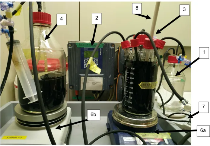
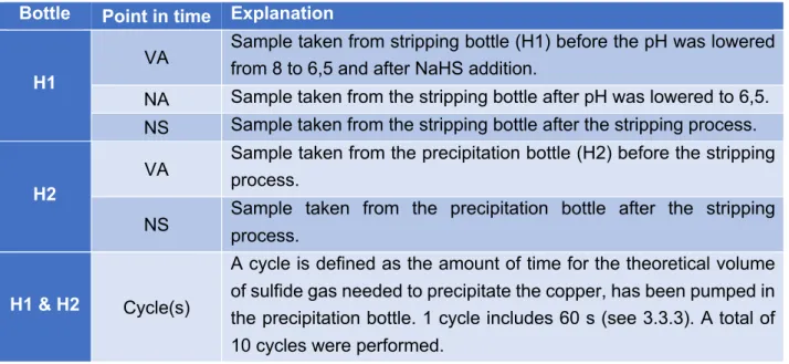
The sulfide acid stripping experimental set-up included a pH controller (DULCOMETER® D1C, Prominent) (number 2 in Figure 3 and Figure 4) connected to a peristaltic pump (VERDERFLEX® VP2) which was attached to a 1 L Schott bottle containing 1 M sulfuric acid (number 1 in Figure 3 and Figure 4). The bottle containing the sulfuric acid was placed on a scale (number 7 in Figure 4) to keep track of the amount of sulfuric acid that was added to the stripping bottle. A sulfide resistant pH electrode (HA405-DXK-S8/120, Elscolab) (number 8 in Figure 4) was inserted in the 1 L stripping bottle (a 3 GL 18 3 GL 25 fermenter, Labor Ochs, Germany). The stripping bottle (number 3 in Figure 3 and Figure 4) contained the synthetic medium represented in Table 4. Beside the pH electrode port, the stripping bottle also contained an acid addition port controlled by the pH controller pump, a liquid sampling port, a liquid suction port (see electrochemical sulfate recovery) and two gas recirculation lines (gas in and gas out). The stripping bottle was placed on a magnetic stirrer (number 6a in Figure 4) to maximize mixing. It was important to make a valve connection at every line so that the stripping bottle could be disconnected from the stripping set-up and anoxically installed in the electrochemical sulfate recovery process.
The precipitation bottle (number 4 in Figure 3 and Figure 4) was a 2 L Schott bottle placed on a magnetic stirrer (number 6b in Figure 4). The bottle was filled with 1 L of the metallurgical wastewater presented in -1 2 3 4 5 6 7 8
9 Electrolysis cell HCO3- solution H2
CO2, O2, H2
Off gas Gas sampling port
Air filter
Liquid sampling port O2
Soil sample HOB microbiome Scrubber 32% NaOH Outside atmosphere 1 M H2SO4 High H2S Low H2S H2S + Cu2+→ CuS(s) pH: 6.5 – 8 SO42-: 8 - 15 g L-1 PID 1 2 3 6 4 5
Table 5. The bottle had 3 connections through the rubber cap. Two of those were gas recirculation lines, connecting the bottle to the stripping bottle and the (explosive atmospheres) ATEX pump (N922FT.29E8LEX, KNF) (number 6 in Figure 3). The third connection was used as a liquid sampling port. A fourth connection was used to connect the precipitation bottle to a gas scrubber of 32% NaOH, but preliminary results indicated that this was unnecessary for the process. The ATEX pump was used to recirculate H2S poor gas from the metal precipitation to the stripping bottle and H2S rich gas from the stripping bottle to the metal precipitation at 0,11 L s-1. Sparging stones were used to maximize gas mixing in the liquid. On the gas recirculation lines, 3-way valves were installed so that samples can be taken during the process. For the stripping process to work at optimum conditions, both the stripping and precipitation bottle and the gas lines needed to be airtight.
Figure 4: Picture taken at the end of a test for the sulfide acid stripping process. The set-up is installed in the fume hood. The ATEX pump is not present in the figure because the pump was installed next to the fume hood.
After the sulfide acid stripping was completed, the stripping bottle was detached from the stripping set-up in a way that the bottle stayed as airtight as possible. The detached stripping bottle will
4 2 1 6b 6a 7 3 8