DECARBONISATION OPTIONS
FOR THE DUTCH STEEL
INDUSTRY
A. Keys, M. van Hout, B. Daniëls
25 november 2019
Decarbonisation options for the Dutch steel industry
© PBL Netherlands Environmental Assessment Agency; © ECN part of TNO The Hague, 2019
PBL publication number: 3723
TNO project no. 060.33956 / TNO publication number: TNO 2019 P11483
Authors
Keys, A., van Hout, M., Daniëls, B.
MIDDEN project coordination and responsibility
The MIDDEN project (Manufacturing Industry Decarbonisation Data Exchange Network) was initiated and is also coordinated and funded by PBL and ECN part of TNO. The project aims to support industry, policymakers, analysts, and the energy sector in their common efforts to achieve deep decarbonisation. Correspondence regarding the project may be addressed to: K.M. Schure (PBL), Klara.Schure@pbl.nl, or A.W.N van Dril (TNO), Ton.vanDril@tno.nl
Production coordination
PBL Publishers
This publication is a joint publication by PBL and ECN part of TNO and can be downloaded from: www.pbl.nl/en. Parts of this publication may be reproduced, providing the source is stated, in the form: Keys. A, van Hout. M, Daniëls. B (2019), Decarbonisation options for the Dutch Steel Industry. PBL Netherlands Environmental Assessment Agency & ECN part of TNO, The Hague.
PBL Netherlands Environmental Assessment Agency is the national institute for strategic pol-icy analysis in the fields of the environment, nature and spatial planning. We contribute to improving the quality of political and administrative decision-making by conducting outlook studies, analyses and evaluations in which an integrated approach is considered paramount. Policy relevance is the prime concern in all of our studies. We conduct solicited and unsolic-ited research that is both independent and scientifically sound.
ECN part of TNO has a twofold mission: to accelerate the energy transition and to strengthen the competitive position of the Netherlands. ECN part of TNO conducts independent and in-ternationally leading research and we stand for an agenda-setting, initiating and supporting role for government, industry and NGOs.
This report was reviewed by TATA Steel IJmuiden. PBL and ECN part of TNO remain respon-sible for the content. The decarbonisation options and parameters are explicitly not verified by the companies.
Inhoud
Summary 4
Introduction
5
1
Current primary steel production
6
1.1 Steel industry in the Netherlands 6
1.2 Company overview 6
1.3 Production overview 6
2
Steel production processes
9
2.1 Process description 9
2.2 Material, energy and CO2 flows 11
3
Steel products and application
17
3.1 Products 17
4
Options for decarbonisation
19
4.1 Technology description 19
Top gas recycling blast furnace (TGR-BF) 20
HIsarna 22
ULCORED 23
ULCOWIN and ULCOLYSIS 25
Comparison of steelmaking technology progress 26
Use of biomass 26
CO2 capture and storage 28
CO2 capture and utilisation 33
Steel recycling 34
Energy efficiency 35
4.2 Material, energy and CO2 flows 35
4.3 Investment and operating costs 47
5
Discussion
52
5.1 Current steelmaking process 52
5.2 Decarbonisation options 52
References
56
Appendix A – current steelmaking process calculations
61
A1. Material and energy calculations for current steel production process 61 A2. CO2 emission data for current steel production process 65
FINDINGS
Summary
• Tata Steel in IJmuiden (TSIJ) is currently the only primary steel producer in the Nether-lands, with a crude steel output of approximately 7 Mt in 2017. The current production process is based on the blast furnace route, with coal as the primary energy source. This technology route has been used since the birth of the site in 1918.
• Significant technological improvements have been made on this technology making Tata Steel IJmuiden one of the most efficient steel producers in the world with blast furnace technology.
• To meet the climate agreement goals for 2030 and 2050, TSIJ is required to change its production process to significantly reduce CO2 emissions, potentially requiring more sub-stantial investments than ever before.
• A demonstration plant of one decarbonisation option, called HIsarna, is operating at IJmuiden. The scale-up on this plant is planned by Tata Steel in Jamshedpur, India. • There are four primary technological options for steel production to decarbonise, as
de-fined by the Ultra-low CO2 Steelmaking program (ULCOS): smelting reduction process (HIsarna) with CCS, top gas recycling blast furnace (TGR-BF) with CCS, direct iron re-duction (by natural gas with CCS or hydrogen) and iron ore electrolysis (ULCOWIN, ULCOLYSIS). Several of these options, as well as the current blast furnace process, have the potential to implement biomass as both a feedstock and a fuel. This could signifi-cantly lower the overall CO2 emissions emitted depending on the extent of implementa-tion.
• The energy requirements of the abovementioned decarbonisation options differ both by energy source and quantity. TGR-BF and HIsarna options are primarily based on coal, di-rect reduction is primarily based on either natural gas or electricity (for hydrogen pro-duction) and ULCOWIN/ULCOLYSIS are primarily based on electricity. Thus, the cost of energy and infrastructure requirements differ greatly for each option. However, energy costs estimates are out of the scope of this report.
• The overnight capital investment cost of each decarbonisation option differs greatly be-tween options. An estimation of overnight capital costs for decarbonisation options comes with a great deal of uncertainty, especially for those options that have not been implemented on an industrial scale yet.
• Investment decisions are not solely based on energy prices and overnight capital invest-ment costs of the steelmaking technology, there are many other relevant considerations. These include government regulations, site independence, public acceptance and re-source availability.
FULL RESULTS
Introduction
This study begins by describing the current, and only, primary steel production facility in the Netherlands with an overview of the process material and energy flows, and how by-products are utilised both within and outside the site. Subsequently, the technological options of de-carbonisation are investigated with potential savings of material and energy, emission reduc-tions, investment costs and infrastructure requirements. The study is part of the MIDDEN project (Manufacturing Industry Decarbonisation Data Exchange Network). The MIDDEN pro-ject aims to support industry, policymakers, analysts, and the energy sector in their common efforts to achieve deep decarbonisation. The MIDDEN project will update and elaborate fur-ther on options in the future, in close connection with the industry.
Scope
In the Netherlands, steel producers include: Tata Steel IJmuiden, North Holland.
Production processes include blast furnace process, basic oxygen furnace process, coking, sintering, pelletizing, gas-fired electricity and heat generation, oxygen production and down-stream steelmaking processes1; products include: crude steel.
The main options for decarbonisation are smelting reduction process (HIsarna) with CCS, top gas recycling blast furnace (TGR-BF) with CCS, direct iron reduction by natural gas with CCS (NG-DR with CCS) or hydrogen (H-DR), iron ore electrolysis (ULCOWIN, ULCOLYSIS).
Reading guide
Section 1 describes the current steel production status at Tata Steel IJmuiden, beginning with an historical overview leading to current steel production levels and environmental im-pacts to provide basic context for the rest of the report. Section 2 provides a description of the current primary steel production process at Tata Steel with material, energy and CO2 flows and how the plant operates logistically for material pre-processing and with third par-ties on site to utilise by-products. In section 3 the crude steel production volume and the main markets that it is processed further to supply to is described. Section 4 introduces the main decarbonisation options with an overview of the process, stage of development of such technologies, and their estimated material, energy and CO2 emission flows. Section 5 dis-cusses each technology’s technical feasibility and resource requirements leading to conclu-sions regarding alternative pathways which Tata Steel can take in the coming decades to meet climate goals.
1 Downstream steelmaking processes such as continuous casting are within the scope of the overall energy
and CO2 emissions of both the current production process and decarbonisation options. However, the
1 Current primary steel
production
1.1 Steel industry in the Netherlands
Steel production in the Netherlands is dominated by primary steel production, the production of graded steel from iron ore. The only large-scale steel producer in the Netherlands is Tata Steel IJmuiden (TSIJ) which applies the blast furnace production process. Steel production at TSIJ primarily supplies customers in three markets: packaging, construction and the automo-tive industry (Tata Steel Europe, 2018).
1.2 Company overview
TSIJ is one of two integrated steel mills that make up Tata Steel Europe, a subdivision of the Tata Steel Group, one of the largest steel groups in the world. The other primary steel pro-duction mill of Tata Steel Europe is based in Port Talbot, UK. There are several downstream processing plants throughout Europe (Tata Steel Europe, 2018), however these are out of the scope of this report. In 1918 the first steel company was established in IJmuiden, at the same location as today, now covering 7.5 km2 on the North Sea coast. The steel mill has un-dergone several company transitions in the past two decades. In 1999 Corus Group was formed following a merger between British Steel and Koninklijke Hoogovens before becoming part of Tata Steel Europe in 2007. Currently, there are more than 9,000 employees based in IJmuiden. TSIJ recorded an annual net turnover of EUR 3.6 billion in 2017. In the same year, a net profit after taxation of EUR 235 million was achieved, an EUR 76 million increase from the previous financial year (Tata Steel, 2017).
1.3 Production overview
TSIJ currently produces just over 7 million tonnes of crude steel annually. Figure 1 displays the historic crude steel production from 2008, showing that production level has remained relatively stable over the past decade (World Steel Association, 2018).
Figure 1. Crude steel production in the Netherlands 2008 – 2017 The main processing units on-site within the scope of this report are:
• 2 coke plants • 1 pelletizing plant • 1 sinter plant • 2 blast furnaces
• 1 basic oxygen furnace plant
• 1 oxygen production plant (3rd party owned) • 3 power generation plants (3rd party owned).
The site layout of the abovementioned processing units, alongside units outside of the scope, is illustrated in Figure 2 (Tata Steel Europe, 2016).
Figure 2. Site layout overview at Tata Steel IJmuiden (Tata Steel Europe, 2016)
0 1 2 3 4 5 6 7 8 2008 2009 2010 2011 2012 2013 2014 2015 2016 2017 Cr ude S te el P ro duc tio n ( M to n)
Steel production is one of the most energy intensive industries in the Netherlands primarily due to the high energy requirement of the two blast furnace plants. The high energy require-ment in the blast furnaces is mainly owed to the primary reaction in the vessel in which iron ore is reduced to pure iron. Electricity plays a significantly smaller part of the overall energy demand in the production process at TSIJ but still consumes 3% of the total electricity con-sumption in the Netherlands. TSIJ generates its own electricity from process gas at several stages in the process which are distributed among four on-site power plants producing an equally significant amount of electricity (as well as heat). The utilisation of process gases to produce electricity and heat leads to approximately half of the CO2 emissions being emitted by the gas-fired power plants and the other half being emitted directly from the steelmaking processes (Tata Steel, 2016).
The World Economic Forum awarded TSIJ into its prestigious community of ‘Lighthouses’, a distinction awarded to manufacturing facilities which are seen as technological leaders (Tata Steel, 2019). Table 1 displays a summary of the performance data at the IJmuiden site; in-cluding crude steel production, CO2 emissions, water consumption and waste disposal and recycling (Tata Steel, 2016).
Table 1. Performance data of Tata Steel IJmuiden 2014-2016 (Tata Steel, 2016).
Unit 2014 2015 2016
Crude steel production Mt 6.866 6.922 6.849
CO2 emissions (scope 1)2 Mt 5.93 6.29 6.30 CO2 emissions (scope 1,2,3)3, 4 Mt 11.95 12.03 12.47 Fresh water consumption m3/t steel 4.65 4.49 4.64
Waste generated kt 228 321 212
Waste disposal to landfill kt 43 57 40
Waste re-used, recycled kt 176 254 164
Environmental complaints 1067 876 1161
2 Scope 1 emissions are direct emissions from owned or controlled sources. Each scope definition is based on
the GHG Protocol Corporate Standard (Greenhouse Gas Protocol, 2019).
3 Scope 2 emissions are indirect emissions from the generation of purchased energy (Greenhouse Gas
Protocol, 2019). This includes the on-site residual gas power plants.
4 Scope 3 emissions are all indirect emissions (not included in scope 2) that occur in the value chain,
2 Steel production
processes
This section provides a description of each of the separate processes involved in steel pro-duction, with associated material, energy and CO2 flows utilising data reported by both TSIJ and also relevant literature to provide good approximations. This forms a basis for the decar-bonisation options to compare energy and CO2 intensities as well as material requirements.
2.1 Process description
There are two main steel production routes used today: (i) blast furnace (BF) process and (ii) electric arc furnace (EAF) process. Globally the former accounts for approximately 70% of steel production. The latter, based on secondary materials such as steel scrap, accounts for 30% (World Steel Association, 2018). TSIJ produces steel via the BF process. Iron ore and coal are the main raw materials, the majority of which are further processed into sinter and pellets (iron ore) and coke (coal) before entering the BF. Pig iron is tapped from the BF and is further processed into crude steel via the basic oxygen furnace (BOF) process in which the carbon content is lowered by oxygen blowing. The BOF typically facilitates 16% of scrap steel to increase recycling rates. The level of scrap steel varies with time depending on price and availability of scrap of sufficiently good quality. The crude steel product leaving the BOF is then processed further into rolls and sheets and can be finished by galvanisation, tin plating or lacquering if required. However, the processing stages after the crude steel product are outside of the scope of this report. Presented below are basic descriptions of the main pro-cesses in the BF propro-cesses route (Daniels, 2002) (EIPPCB, 2013) (Gielen & Van Dril, 1997).
Coke production
Coke (and coke breeze) is a carbon-containing solid material produced in a coke oven by batch pyrolysis of coking coal. The reaction takes place at temperatures above 1000 °C and each batch lasts approximately 16-20 hours. The coke is then cooled by the addition of water before it can be utilised. The main by-product of this process is coke oven gas (COG), which has a typical volumetric composition of H2 = 57.3%, CH4 = 23.7%, CO = 6.6%, CO2 = 2.6%, N2 = 7.2% and other hydrocarbons = 2.4% (Bieda, Grzesik, Sala, & Gaweł, 2015). Part of the COG is recycled and combusted to provide heat to the oven, whilst the remainder of the COG is combusted to heat the BF, for electrical power generation and in the downstream steelmaking processes. Raw COG contains valuable by-products including tar, sulphur com-ponents, ammonia and light oil (BTX) that are further processed and sold. TSIJ has two cok-ing plants with a coke oven fircok-ing system and a process gas treatment unit to recover the emitted COG. The overall thermal efficiency of the coke oven system is approximately 80%. The coking plant is one the most energy intensive parts of the steelmaking process, as well as one of the costliest. Hence, TSIJ is continually trying to increase the direct intake of pul-verized coal into the BF to reduce the coke requirements. Currently, TSIJ produces more coke than it requires, with the excess being sold to third-parties.
Sinter and pellet production
Iron ore occurs naturally as lump ore and fine ore. BFs are not capable of solely using fine ore as the feedstock and so agglomeration of fine ore is necessary. Lump ore may be possi-ble to use solely, however is scarcer and more expensive than producing sinter and pellets from fine ore. The sintering process consists of heating up fine ore, alongside additives such as limestone, causing it to agglomerate into larger aggregates with a porous structure. A po-rous structure is important as the blast furnace is a counter-flow reactor and so gases must be able to pass through the iron ore material. In the pelletising process, the fine ore is mixed with additives, such as limestone and olivine, in a wet condition and pellets are formed with a binder and subsequently baked. Sinter and pellets are used in the BF, alongside a small proportion of lump ore in some modern BFs, such as at TSIJ.
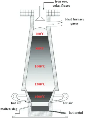
Blast furnace
A BF is used to reduce (remove oxygen) iron ore to produce a hot liquid pig iron with a car-bon content of 4% (Abspoel, 2018). Coke, sinter and pellets are the primary components fed into the top of the furnace and hot oxygen enriched air and pulverised coal are blasted from the bottom through the porous structures (tuyeres). This process results in partial combus-tion of the carbon from coke and coal, producing reducing gases (containing carbon monox-ide) that heat the furnace resulting in liquid pig iron which is subsequently tapped off at the bottom and transported to the BOF. The ideal chemical equation of such reducing reaction from haematite (one of the most commonly used iron ore) is as follows (Gielen & Van Dril, 1997):
𝐹𝐹𝐹𝐹2𝑂𝑂3+ 3𝐶𝐶𝑂𝑂 → 2𝐹𝐹𝐹𝐹 + 3𝐶𝐶𝑂𝑂2.
Slag is also produced as a by-product and tapped off separately at the bottom of the furnace to be sold on to other industries such as cement and asphalt. Excess reducing gases are used for power generation and recycled for heat generation or for other processes. A basic sche-matic of the input and output material flows are displayed in Figure 3 (Gao, Ge, & Jian, 2014).
Basic oxygen furnace
The primary reaction in the BOF is the oxidation of carbon in the pig iron by the injection of oxygen. The degree of oxidation of carbon is varied depending on the desired steel product specification. The overall process is exothermal and hence the excess energy allows the pos-sibility of increased levels of scrap steel to be added in the furnace. Scrap steel is also com-monly inputted alongside pig iron in the BOF with the purpose of temperature control and to reduce the amount of pig iron required to produce crude steel. Slag is produced as a by-product from the oxidation of impurities such as silicon, manganese, phosphorus and sul-phur.
Oxygen production
Oxygen is produced from air by a cryogenic separation unit owned and operated by Linde. Oxygen is required in both the BF and BOF, but at slightly different purities. The BF typically requires an oxygen purity of greater than 95vol% primarily for oxygen enrichment of the hot air blast. The BOF requires an oxygen purity of greater than 99.5vol% for the main process of blowing into the furnace. A higher nitrogen content may adversely affect the steel quality.
2.2 Material, energy and CO
2flows
To gain a good understanding of the current steelmaking process, material and energy flows are calculated to match the current situation as closely as possible. This has been achieved by a combination of data provided by TSIJ and publicly available data. Material, energy and CO2 flows differ somewhat each year. The presence of multiple sources to formulate these flows have left some ambiguity due to different reporting years. Thus, an attempt has been made to scale energy quantities to match totals reported for 2017, as reported by CBS (2017).
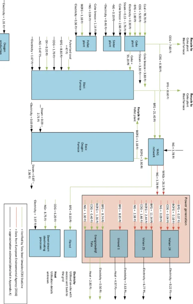
Figure 4 and Figure 5 display an overview of the material and energy flows respectively throughout the entire steelmaking process, including the work arising gases (WAGs) based power generation units. The figure identifies the source from which the value has been rived. Streams that required assumptions to balance the material and energy flows are de-tailed in Appendix A.
Power generation from WAGs is a significant part of the steelmaking processes in terms of electricity generation and subsequent CO2 emissions. There are four main power generation units at TSIJ: Velsen 24, Velsen 25, IJmond 1 (owned and operated by Vattenfall) and a TSIJ -owned CHP plant known as Energiebedrijf Tata for the purpose of this report. Table 2 states the basic characteristics and a short explanation of these power generation units.
Steam generation and utilisation is difficult to determine and thus ranges based on EIPPCB (2013) are used. An exception is the output of the coke plant in which an assumption has been made that coke dry quenching (with heat recovery in the form of steam) is applied and hence a single value is given.
Table 2. Description of power generation plants
Name Technology Electricity capacity (MWel) Heat capacity (MWth) Main fuel Other fuel(s) Description Velsen 24 CCGT 460 - BFG BOFG, COG, Natural gas Serves as a backup unit when the other units are out of oper-ation or when de-mand of electricity is greater (Vattenfall, 2019). Velsen 25 CCGT 375 - BFG BOFG, COG, Natural gas
Base load unit that can run entirely on BFG, however natural gas is sometimes added to balance fluctuation in BFG supply (Vattenfall, 2019).
IJmond 1 CHP 144 105 BFG - Base load unit that can run entirely on BFG and produces both electricity and heat (Vattenfall, 2019). Energiebedrijf Tata CHP 175 976 - BFG, BOFG, COG, natural gas Operated by TSIJ with a mixture of WAGs and natural gas inputted.
Figure 6 displays the total final energy consumption of the main steelmaking processes, ex-cluding the power generation units. The blast furnace is the most energy intensive process, due to the large input of both coke and pulverized coal. The coke plant is the second-most energy intensive process with a large input of coking coal to be processed into C for the blast furnace.
5 0.5 PJ of electricity is reported to be generated annually and 8000 running hours are assumed to calculated
the capacity (CBS, 2017).
6 2.8 PJ heat is reported to be generated annually and 8000 running hours are assumed to calculated the
Figure 6. Total energy consumption distribution in steelmaking process
The main underlying interest in this report concerns the resulting CO2 emissions of the pro-cess and how they are distributed within the propro-cess itself. To calculate this, a combination of CO2 emission factors and carbon content of materials and fuels are used. Appendix A states the assumed CO2 emission factors and carbon content of all materials and fuels in the process. Presented below is the methodology used for calculating the CO2 emissions per pro-cess with a non-specific example (Figure 7). A true calculation is not given for conciseness of this report. 1% 1% 38% 50% 1% 8% Sinter plant Pellet plant Coke plant Blast furnace Basic oxygen furnace Oxygen production Downstream steelmaking processes
Figure 7. Schematic of CO2 emission calculation example (𝑡𝑡𝑡𝑡𝑡𝑡𝑡𝑡𝑡𝑡 𝐶𝐶𝑂𝑂2− 𝑖𝑖𝑖𝑖𝑖𝑖𝑖𝑖𝑡𝑡 [𝑀𝑀𝑡𝑡𝑡𝑡𝑖𝑖]) − (𝑡𝑡𝑡𝑡𝑡𝑡𝑡𝑡𝑡𝑡 𝐶𝐶𝑂𝑂2− 𝑡𝑡𝑖𝑖𝑡𝑡𝑖𝑖𝑖𝑖𝑡𝑡 [𝑀𝑀𝑡𝑡𝑡𝑡𝑖𝑖]) = 𝑑𝑑𝑖𝑖𝑑𝑑𝐹𝐹𝑑𝑑𝑡𝑡 𝐶𝐶𝑂𝑂2 𝐹𝐹𝑒𝑒𝑖𝑖𝑒𝑒𝑒𝑒𝑖𝑖𝑡𝑡𝑖𝑖𝑒𝑒 𝑓𝑓𝑑𝑑𝑡𝑡𝑒𝑒 𝑖𝑖𝑑𝑑𝑡𝑡𝑑𝑑𝐹𝐹𝑒𝑒𝑒𝑒 1 [𝑀𝑀𝑡𝑡𝑡𝑡𝑖𝑖] �𝑖𝑖𝑖𝑖𝑖𝑖𝑖𝑖𝑖𝑖 1 [𝑃𝑃𝑃𝑃]×𝑖𝑖𝑖𝑖𝑖𝑖𝑖𝑖𝑖𝑖 1 𝑒𝑒𝑒𝑒𝑖𝑖𝑒𝑒𝑒𝑒𝑖𝑖𝑒𝑒𝑖𝑖 𝑓𝑓𝑓𝑓𝑓𝑓𝑖𝑖𝑒𝑒𝑓𝑓 �𝑘𝑘𝑘𝑘𝑘𝑘𝑘𝑘2𝐺𝐺𝐺𝐺 � 1000 + 𝑖𝑖𝑖𝑖𝑖𝑖𝑖𝑖𝑡𝑡 2 [𝑀𝑀𝑡𝑡𝑡𝑡𝑖𝑖] × 𝑖𝑖𝑖𝑖𝑖𝑖𝑖𝑖𝑡𝑡 2 𝑑𝑑𝑡𝑡𝑑𝑑𝑐𝑐𝑡𝑡𝑖𝑖 𝑑𝑑𝑡𝑡𝑖𝑖𝑡𝑡𝐹𝐹𝑖𝑖𝑡𝑡 [−] × 𝑒𝑒𝑒𝑒𝑚𝑚𝑒𝑒𝑓𝑓𝑖𝑖𝑚𝑚𝑓𝑓𝑓𝑓 𝑒𝑒𝑓𝑓𝑒𝑒𝑒𝑒 𝐶𝐶𝐶𝐶2�𝑚𝑚𝑚𝑚𝑚𝑚𝑘𝑘� 𝑒𝑒𝑒𝑒𝑚𝑚𝑒𝑒𝑓𝑓𝑖𝑖𝑚𝑚𝑓𝑓𝑓𝑓 𝑒𝑒𝑓𝑓𝑒𝑒𝑒𝑒 𝐶𝐶 �𝑚𝑚𝑚𝑚𝑚𝑚𝑘𝑘��M − �𝑡𝑡𝑖𝑖𝑡𝑡𝑖𝑖𝑖𝑖𝑡𝑡 1 [𝑃𝑃𝑃𝑃] × 𝑡𝑡𝑖𝑖𝑡𝑡𝑖𝑖𝑖𝑖𝑡𝑡 1 𝐹𝐹𝑒𝑒𝑖𝑖𝑒𝑒𝑒𝑒𝑖𝑖𝑡𝑡𝑖𝑖 𝑓𝑓𝑡𝑡𝑑𝑑𝑡𝑡𝑡𝑡𝑑𝑑 �𝑘𝑘𝑘𝑘𝐶𝐶𝑂𝑂 2 𝐺𝐺𝑃𝑃 � 1000 � = 𝑑𝑑𝑖𝑖𝑑𝑑𝐹𝐹𝑑𝑑𝑡𝑡 𝐶𝐶𝑂𝑂2 𝐹𝐹𝑒𝑒𝑖𝑖𝑒𝑒𝑒𝑒𝑖𝑖𝑡𝑡𝑖𝑖𝑒𝑒 [𝑀𝑀𝑡𝑡𝑡𝑡𝑖𝑖]
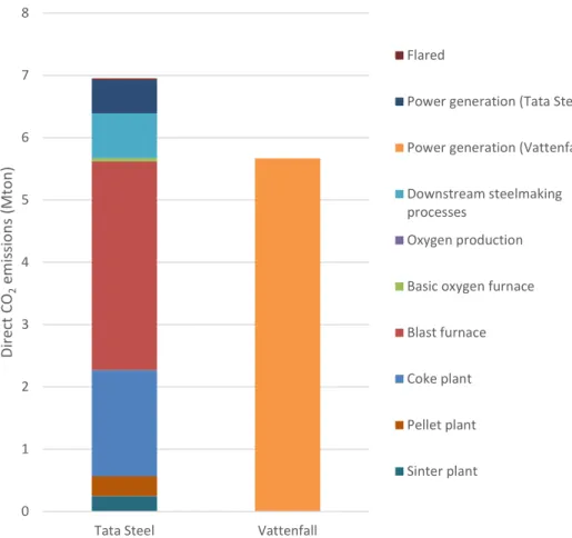
Figure 8 displays the calculated direct CO2 emissions per process, the emission distribution between processes and the specific emissions per tonne of crude steel. The total direct CO2 emissions and specific direct CO2 emissions are compared to the reported value from TSIJ in 2017 (Dutch Emissions Authority, 2019). The calculated values are slightly less than what is reported but are broadly similar, with differences likely arising from different values assumed for CO2 emission factors and carbon content of materials.
Figure 8. Calculated annual direct CO2 emission distribution of steelmaking units
and power generation plants
0 1 2 3 4 5 6 7 8
Tata Steel Vattenfall
Di re ct C O2 em issi on s ( M to n) Flared
Power generation (Tata Steel) Power generation (Vattenfall) Downstream steelmaking processes
Oxygen production Basic oxygen furnace Blast furnace Coke plant Pellet plant Sinter plant
3 Steel products and
application
Steel is an essential product for a wide range of applications such as buildings, cars and kitchen appliances. Steel produced in the Netherlands is consumed both within the Nether-lands and exported. Demand for steel is strongly correlated with population and the stage of economic development of a country. The projection of EU steel demand conducted by Krishnan (2017) predicts that demand will decline from 161 Mt in 2016 to 130 Mt in 2050. This would suggest that in the Netherlands, production is unlikely to increase or decrease dramatically within this period.
This chapter presents an overview of the product range produced by Tata Steel in Europe. Future steel demand and the markets in which steel operates in are important when evaluat-ing low-carbon steelmakevaluat-ing technologies. Not all required steel production levels and quality can be met by all steelmaking technologies in the coming decades. For example, some of the high grade steels that TSIJ currently produce cannot be made by using only scrap steel.
3.1 Products
The primary markets that Tata Steel in Europe operate in are engineering, automotive, pack-aging and construction. Within each of these markets, Tata Steel produce a wide range of in-dustry specific products as well as generic products. The main products in these markets are listed in Table 3. A breakdown of sales by market sector and by product for Tata Steel Eu-rope is illustrated in Figure 9 and Figure 10 (Tata Steel, 2019). Primary steel production by Tata Steel Europe takes place in the Netherlands and UK and this steel is exported to a range of downstream manufacturing operations throughout Europe. Hence, is it difficult to identify the product range solely from Dutch produced steel. The properties and specifications of products is out of the scope of this report but is readily available in the Tata Steel Europe product and service catalogue (Tata Steel, 2018).
Engineering Automotive Packaging Construction Hot-rolled Direct-rolled Cold-rolled Metallic coated Pre-finished steel Electro-plated steel Electrical steels Tubes Coretinium Raw materials Electrical steels Hot-rolled Direct rolled Cold-rolled Metallic coated Electro-plated steel Tubes Tailor Welded Blanks Aurora Online Structural Floor plate Materials and finishes Metallic coated Walls Roofs Renewables Tubes Other Tinplate ECCS Protact Blackplate
Figure 9. Tata Steel in Europe: sales by market sector (%sales volume)7
Figure 10. Tata Steel in Europe: sales by product (%sales volume)
7 Manufactured goods includes sales to Engineering, Lifting & Excavating, Independent Service Centres and
semi-finished products.
32%
32% 22%
13%
Manufactured goods Automotive Construction Packaging
26% 24% 12% 9% 8% 7% 6% 3% 3% 2%
Metallic coated Hot rolled Packaging steel
Cold rolled Tubes Organic coated
4 Options for
decarbonisation
This chapter presents the possible technology options that can apply to the Dutch steelmak-ing industry to significantly reduce CO2 emissions. Firstly, a description of some of the possi-ble technology options and the current status of implementation is given. Then, an
estimation of the material and energy flows are described and presented schematically. Fol-lowing this, a comparison is made between options based on energy requirements and CO2 emissions emitted. Finally, a comparison is made between options based on estimations of the operating and overnight capital investment costs.
4.1 Technology description
There are a broad range of alternative technologies that have the potential to significantly reduce CO2 emissions in steelmaking. Several different programmes have been established to develop these technologies, of which the main programmes are: ULCOS (EU), COURSE50 (Japan), POSCO (South Korea) and AISI (USA). From these programmes, ULCOS has the most extensive research scope (Junjie, 2018). The technologies being developed by these programmes all fall under the following categories and some examples are given:
• Revamped blast furnace: TGR-BF, IGAR
• Direct reduction ironmaking: ULCORED, MIDREX, HYL. HYBRIT, H2Future • Smelting reduction ironmaking: HIsarna, COREX, FINEX
• Iron ore electrolysis: ULCOWIN, ULCOLYSIS, SIDERWIN • Carbon capture and storage/utilisation.
For simplicity, and to avoid repetition of similar technologies, only some of the possible tech-nologies are selected for further explanation and analysis. The ULCOS programme has identi-fied the main options that it deems to have the most potential, covering all of the above mentioned categories: TGR-BF, ULCORED, HIsarna, ULCORED, ULCOWIN and ULCOYSIS. The ULCOS program has also identified a number of supporting technologies alongside these: hy-drogen direct reduction steelmaking (H-DR), biomass-based steelmaking and carbon capture and storage (CCS). Due to these technologies covering the main alternative technology cate-gories as well as having the most extensive research and available data, these technologies are selected for further consideration. However, this does not go to say that other technolo-gies are not possible or relevant.
The Ultra-low CO2 Steelmaking programme (ULCOS) was set up by the European Steel Tech-nology Platform in 2004. The aim of the program was to develop new low-carbon steelmak-ing technologies that have the potential to reduce CO2 emissions per tonne of steel by 50% from the 2004 best level of 2 tonnes of CO2 per tonne of steel to 1 tonne of CO2 per tonne of steel by 2050 (Junjie, 2018). The first phase (ULCOS I, 2004-2010) involved theoretical re-search and pilot-scale testing, costed EUR 3.5 million and received EUR 2 million in funding. The second phase (ULCOS II, 2010-present) takes four pilot technology projects that are deemed to have the greatest potential to develop further towards industrial scale (Abdul Quader M., Ahmed, Ariffin Raja Ghazilla, Ahmed, & Dahari, 2015).
Below, a description and the current implementation progress of the following selected alter-native technologies are presented, with the option of supporting technology such as CCS, hy-drogen and biomass for applicable options.
• TGR-BF • HIsarna • ULCORED • ULCOWIN • ULCOLYSIS.
Top gas recycling blast furnace (TGR-BF)
This technology involves modification of the existing BF to include top gas recycling. The re-ducing agents (CO and H2) are recycled from the gas leaving the BF top after CO2 removal. Recycling this stream reduces the demand for coke and hence reduces energy use and car-bon emissions from the coking plant. TGR-BF primarily consists of the following modifications as compared to the conventional BF (van der Stel, et al., 2014):
• Injection of reducing top gas components CO and H2 into the shaft and/or hearth tuyeres.
• Lower fossil-based carbon input due to lower coke rates.
• Use of pure oxygen in place of hot air blast at the hearth tuyere (elimination of nitro-gen).
• Recovery of high-purity CO2 from the top gas for underground storage.
Four versions of TGR-BF were originally tested. However, version 2 has been rejected due to a lower carbon saving than expected and challenging technology required to heat the recycle gas in two steps, by a recuperator and by partial oxidation.
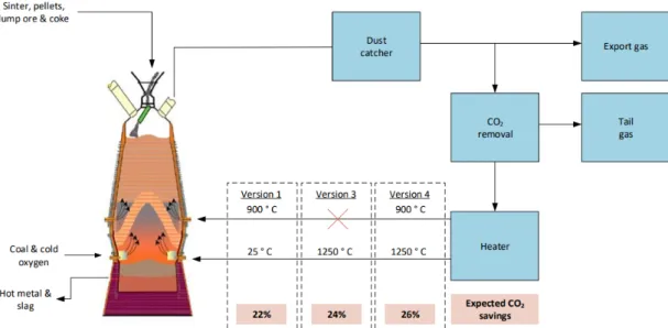
The three remaining versions are described below and illustrated in Figure 11 (Abdul Quader M. , Ahmed, S, & Nukman, 2016). The versions differ mainly with regard to the level of pre-heating of the CO2-free top gas and the location of the injection of the top gas in the blast furnace. Note: the top gas exits the furnace at a temperature of approximately 100 °C and the CO2 removal is achieved by VPSA (Suopajärvi, 2014).
Version 1 – part of the CO2-free top gas is recycled, preheated to 900 °C and injected into the BF through the tuyeres in the furnace stack. Another part of the CO2-free cold top gas (25 °C), alongside oxygen and pulverized coal, are injected into the blast furnace through the tuyeres in the furnace hearth. The expected CO2 saving from this version is 22% exclud-ing CCS (Junjie, 2018).
Version 3 – the CO2-free top gas is preheated to 1250 °C and injected into the BF through the tuyeres in the furnace hearth. The expected CO2 saving from this version is 24% exclud-ing CCS (Junjie, 2018).
Version 4 – part of the CO2-free top gas is preheated to at 900 °C and injected into the BF through the tuyeres in furnace stack. Another part of the CO2-free top gas is preheated to 1250 °C and , alongside oxygen and pulverized coal injected at into the blast furnace
through the tuyeres in the furnace hearth. The expected CO2 saving from this version is 26% excluding CCS (Junjie, 2018).
Figure 11. Simplified process flow diagram of considered variations of TGR-BF The operation of the three versions have been tested in 2007 on an experimental BF (E-BF) in the facilities of LKAB, a Swedish iron ore manufacturer and supplier. Some additional tech-nological additions were required to be implemented on the E-BF, this included a vacuum pressure swing adsorption (VPSA) device to remove the CO2 from the top gas and vertical gas injection devices at the tuyeres of the furnace stack (Junjie, 2018).
The most notable results achieved during the tests at these facilities are as follows (Junjie, 2018):
• On average, for the three versions, the carbon input decreased from 470 kg/thm to 350 kg/thm (thm = tonne of hot metal).
• The top gas recovery rate of version 3 can reach 72%8, with carbon consumption re-duced by 15%. The top gas recovery rate of version 4 can reach 90%, with carbon consumption reduced by 24%. As more CO and H2 is injected, the reduction rate of iron ore increases and hence the consumption of coal and coke is reduced. The con-sumption of coal and coke is reduced at a rate of 17 kg for every additional cubic meter of CO and H2.
• VPSA unit operated stably, processing 97% of the recycled top gas in the blast fur-nace. The injected gas contained, on average, 2.67vol% of CO2 with a CO recovery rate of 88%, thus achieving the required composition and quantity for the process. • In conjunction with CCS units, the quantity of CO2 is proved to be able to be reduced
by 1270 kg/thm with TGR-BF. This is 76% of the total CO2 emissions in the ironmak-ing process. However, the version in which this result is achieved is not explicitly stated.
In conclusion, the test results validated the operation, safety, efficiency and stability of the TGR-BF. Version 4 proved to have the greatest emissions reduction potential and hence is the priority of the next round of testing with an industrial-scale BF. TGR-BF also has the po-tential to substitute coal with a source of biomass for further emission reduction, although tests have not been carried out for this.
8 Top gas recovery rate refers to the amount of top gas that is recycled back into the blast furnace rather
HIsarna
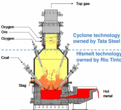
A conventional BF requires the pre-processing of raw materials; iron ore into sinter and pel-lets and coal into coke. HIsarna is based on a smelting reduction process, eliminating the pre-processing steps by allowing the raw materials to be injected directly into a reactor as powders. Throughout the HIsarna reactor, the temperature is above the melting point of iron, allowing iron ore to instantly melt and subsequently converted into liquid iron. At the top of the reactor (CCF cyclone), the temperature is increased further by the addition of oxy-gen to react with carbon monoxide present. The cyclone part of the reactor creates a turbu-lent environment that allows greater contact time for the hot gas to enter at the top and partially reduce and melt the iron ore. The degree of partial reduction in the cyclone is typi-cally in the range of 10-20% (Junjie, 2018).
The molten iron ore then falls to the bottom of the vessel (smelter) and comes into contact with powder coal which is injected at a high speed in the bottom after being decomposed and preheated in a coal decomposition furnace. The reaction of carbon from the powder coal with the melted iron ore creates liquid iron. The temperature in the smelter is around 1400-1450 °C with 4vol% dissolved carbon (Junjie, 2018).
The partly combusted gas leaving the smelter is then internally circulated to provide hot fuel gas to the cyclone. The pure liquid iron is then tapped off at the bottom for further pro-cessing (Tata Steel, 2018). A simplified schematic of this process is displayed in Figure 12 (Junjie, 2018).
Figure 12. Simplified schematic of the HIsarna process with CCS
If implemented on an industrial scale, HIsarna is claimed to produce at least 20% lower CO2 emissions and use at least 20% less energy compared to conventional steelmaking process. It is also ideally suited for CCS due to the absence of nitrogen in the gases, the compressibil-ity of the gas due to sufficient CO2 content and the once-through gas flow nature. Taking into account CCS, up to 80% CO2 reduction can be achieved compared to the conventional steelmaking process (Tata Steel, 2018). Asides from energy and carbon savings, and hence cost reduction, HIsarna can eliminate 90% of the process phosphorous to slag. This allows
the use of cheaper, high-phosphorous iron ore which would not normally be accepted in the conventional process.
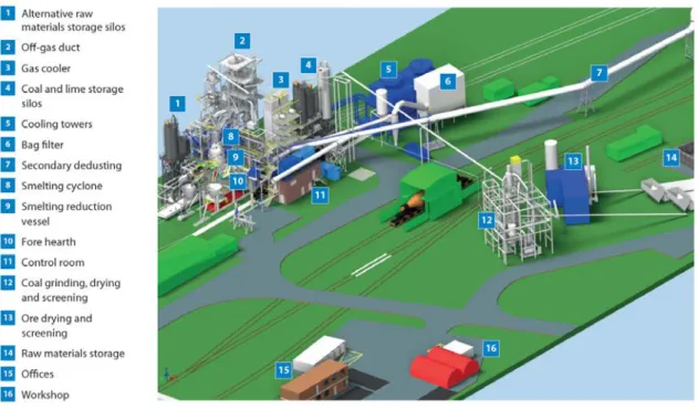
A HIsarna pilot plant has been successfully designed and developed at TSIJ since 2011. The project has been jointly developed by Tata Steel and the mining company Rio Tinto. Further testing and development is being undertaken alongside additional partners: ArcelorMittal, ThyssenKrupp, Voestalpine and technology supplier Paul Wurth. In addition to the partner companies, the European Union has provided significant funding for the plant and in October 2017, a six-month test campaign was carried out proving that liquid steel can be produced for high running hours. It is estimated that this campaign costed approximately EUR 25 mil-lion. Following the success of this campaign, the next stage is intended to design, construct and test a larger-scale pilot plant with an estimated investment of EUR 300 million. It is an-ticipated that this will have to go through several years of testing 2 to 3 times the size of the current pilot plant at IJmuiden with a production capacity up to 10 times greater (Tata Steel, 2018). In November 2018, it was announced that the new large-scale pilot plant will be built in Jamshedpur, India. The plant is planned to initially produce 400,000 thm/year with a scale up to 1 million thm/year eventually. The new plant does not signal the closure of the current pilot plant at IJmuiden, which is currently producing 60,000 thm/year (Process Control, 2018). An illustration of the HIsarna pilot plant layout at TSIJ is shown in Figure 13 (Tata Steel, 2018).
Figure 13. Layout of HIsarna pilot plant at TSIJ
ULCORED
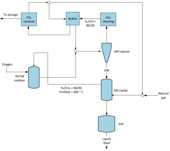
ULCORED is a direct reduction technology that produces direct-reduced iron (DRI) in a shaft furnace. The main features of ULCORED compared to other direct reduction-based technolo-gies are as follows:
• The use of pure oxygen in the shaft furnace produces a flue gas with no or low nitro-gen content, making CO2 capture easier.
• Reduced natural gas requirements due to the recycle of the flue gas after CO2 re-moval to act as a reducing agent.
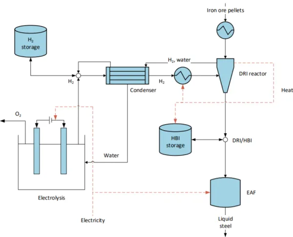
A schematic illustration of natural gas-based ULCORED is displayed in Figure 14 (Sikstrom, 2013). With hydrogen as the reducing agent, the only by-product in the shaft furnace is wa-ter. This means that zero CO2 emissions are produced in the ironmaking stage, with the overall emissions being entirely associated with hydrogen-production, pellet plant, EAF and downstream steelmaking processes. The use of hydrogen in the ULCORED process is re-searched less than that of natural gas or coal and thus there is still a lack of knowledge on its potential. A schematic illustration of hydrogen direct reduction, not specific to ULCORED, is displayed in Figure 15 (Ahman, et al., 2018).
Figure 15. Example schematic of hydrogen-based direct reduction
ULCOWIN and ULCOLYSIS
Electrochemical reduction of iron oxide forms the basis of both ULCOWIN and ULCOLYSIS technologies. ULCOWIN utilises direct electrolysis powered by electricity to produce iron and oxygen from iron ore particles submerged in an alkaline electrolyte (NaOH) solution at a temperature of ~110 °C. A schematic of the basic working principle of the ULCOWIN process is displayed in Figure 16 (Moseley & Garche, 2014). This electrolysis technology is emission-free when powered by renewable electricity sources. The overall emissions are hence fully dictated by pre-treatment processes, EAF and downstream processes. During the ULCOS I phase, an iron purity of 99.98% was achieved with an energy consumption of 9.36 to 10.8 GJ per tonne of pure iron. However, the production rate was very low at around 5 kg pure iron per day.
One solution to overcome the production rate constraint, is to dissolve iron ore in a molten oxide solution at 1600 °C, higher than the melting point of iron, using electrical direct reduc-tion. This technology is known as ULCOLYSIS. The (inert) anode is submerged in the electro-lyte solution and electrical current is passed between this anode and a liquid iron pool connected to the circuit as the cathode. This produces oxygen gas at the anode and liquid iron at the cathode. Both technologies based on iron ore electrolysis are currently the least developed of the four ULCOS technologies. However, the electrolysis process itself is very mature with its wide implementation in smelting metal such as aluminium, zinc and nickel (Junjie, 2018) (Abdul Quader M. , Ahmed, Ariffin Raja Ghazilla, Ahmed, & Dahari, 2015).
Figure 16. Basic schematic of iron ore electrolysis
Comparison of steelmaking technology progress
Table 4 displays a comparison of the TRL (technology readiness level) of decarbonisation op-tions to give context to their possible deployment in the Netherlands (IEA, 2019) (ICF Consulting Services Limited and Fraunhofer ISI, 2019).
Table 4. Comparison of TRL of steelmaking decarbonisation options
Technology TRL
TGR-BF 6 - 7
HIsarna 5
ULCORED (natural gas) 2-4
H-DR 79
ULCOWIN/ULCOLYSIS 5-6 (ULOCWIN)
<5 (ULCOLSYIS)
Use of biomass
Using biomass as a reducing agent has the potential to achieve zero and even negative net carbon emissions. This is possible because the carbon cycle is short, the CO2 is recently ex-tracted from the atmosphere by plants, as opposite to a very long time ago in the case of fossil fuels. Asides from this, the sulphur content in biomass is typically low, meaning that less capital is required for sulphur removal from iron. Although the use of biomass is much
9 This refers to more developed direct reduction technologies (e.g. HYBRIT), rather than
less technologically complex than some of the other low-carbon technologies, it has several important conditions to fulfil: (i) the harvesting of biomass does not degrade its environmen-tal conditions (such as soil, water, air and biodiversity) for future use. (ii) The use of biomass does not threaten food prices and the habitation of humans (Abdul Quader M., Ahmed, S, & Nukman, 2016).
Biomass-based steel production is already in practice on a small scale. Charcoal from euca-lyptus trees in Brazil is being used in a small-scale BF as 100% of the feedstock. However, the use of eucalyptus trees in Europe is not realistic, but it does show the potential and thus research and development of other biomass sources which are more feasible in Europe is worth investigating.
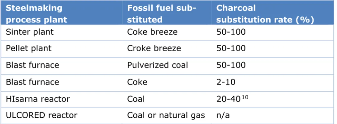
Charcoal is cited as the most feasible biomass material for substitution and its possible fossil fuel substitution range are given in Norgate, Haque, Somerville, & Jahanshahi (2012). Tests on HIsarna are currently increasing charcoal substitution and a target of 40% charcoal sub-stitution was made for 2017-18. Although this goal has not been seen to be proven yet, it is assumed technically possible for this report. An important consideration is that although it may be technically possible to substitute charcoal 100%, this may only be feasible at a small scale and not on an industrial scale. Unfeasibility of such high substitution may arise from lack of spatial requirements (lower energy density of some biomass sources) or the undesira-ble mechanical properties of the selected biomass material. For simplicity and lack of rele-vant literature on industrial scale applicability, the upper limits from Norgate, Haque, Somerville, & Jahanshahi (2012) are used. The possible charcoal substitution rates are sum-marised in Table 5. The possible substitution rate for ULCORED is not cited in literature and thus will not be included in further results to avoid making conclusions on uncertain data.
Table 5. Degree of implementation of charcoal per process for applicable steelmak-ing process plants
Steelmaking process plant
Fossil fuel sub-stituted
Charcoal
substitution rate (%)
Sinter plant Coke breeze 50-100
Pellet plant Croke breeze 50-100
Blast furnace Pulverized coal 50-100
Blast furnace Coke 2-10
HIsarna reactor Coal 20-4010
ULCORED reactor Coal or natural gas n/a
CO
2capture and storage
The addition of carbon capture and storage (CCS) to the various decarbonisation options can reduce the CO2 emissions significantly without any major changes in the steelmaking pro-cess. The high level of emission reduction is possible because of the presence of single fixed points where CO2 is released and easily accessible. In some cases, the CO2-containing flue gas has been purified from nitrogen, thus making the separation of CO2 much easier. After separation, CO2 must be compressed and in some cases cooled and then transported via pipelines or shipping/road vehicle tankers to an appropriate location for long-term storage (e.g. geological reservoirs in the deep ocean, or by the mineralisation of other compounds, chemical reactants or rocks) (Abdul Quader M. , Ahmed, S, & Nukman, 2016). TSIJ have ini-tiated a CCS project called Athos which intends to conduct a feasibility study by 2022 and start storing CO2 in 2027. It is initially estimated that the initial design will facilitate 5±1 MtCO2/year to be stored in empty gas fields for at least 20 years (van Bracht & Braun, 2018).
CO2 capture within the steelmaking industry, must be considered differently than to other sectors such as the power sector. Conventionally, CCS can be classified as pre-combustion, post-combustion or oxyfuel combustion. However, CCS in the steelmaking process does not always fall directly into one of these categories. CCS for steelmaking primarily concerns cap-turing emissions from the reduction of iron ore, rather than combustion or oxidation (Global CCS Institute, 2010). Ultimately, the most appropriate method of CCS is dependent upon the particular steelmaking technology used. The main CO2 capture technologies being explored for steelmaking are discussed below.
Absorption
Absorption can be either physical or chemical and takes place in the bulk of the gas over two main stages. Firstly, a physical or chemical solvent is used to capture CO2 in the first reactor (absorber) and then in the second reactor (stripper), the solvent is recovered, leaving a CO2 pure stream. Chemical absorption processes are considered the most suitable for removing CO2 from the BF steelmaking process, however, the process is expensive due to the large amount of thermal energy required to break the strong bonds formed between the solvent and CO2. Amines, commonly monoethanolamine (MEA), are often used as the solvent in chemical absorption due to its good selectivity and capture efficiency properties. However, MEA has some drawbacks such as equipment corrosion, solvent degradation and low CO2 loading capacity. Other chemical convents being investigated include ammonia, which has shown to have a higher capture efficiency, higher loading capacity, lower costs and lower en-ergy requirements compared to MEA. Despite these benefits, its high volatility and ability to easily form precipitates cause it to be easily lost in the process and thus this challenge is yet to be overcome (Abdul Quader M. , Ahmed, Ariffin Raja Ghazilla, Ahmed, & Dahari, 2015). Figure 17 illustrates the basic principles of the chemical absorption process (Abdul Quader M. , Ahmed, Ariffin Raja Ghazilla, Ahmed, & Dahari, 2015).
Figure 17. Schematic of chemical absorption-based CCS
Adsorption
Adsorption can occur by physical (physisorption) or chemical (chemisorption) bonding. Asides from the type of bonding, the different sorption technologies differ primarily by the nature of the CO2-absorbing material (such as zeolite or activated carbon) and on the pro-cess of absorption and desorption on the respective material (changes in temperature or pressure) (Global CCS Institute, 2010). The main commercially available CCS adsorption technologies in the steelmaking industry are Pressure Swing Adsorption (PSA) and Vacuum Pressure Swing Adsorption (VPSA) (Abdul Quader M. , Ahmed, Ariffin Raja Ghazilla, Ahmed, & Dahari, 2015). These technologies separate CO2 by loading the gas into the adsorption vessel under pressure and then separating it by swinging the pressure to atmospheric or a vacuum, respectively. One of the most promising PSA technologies for the steel sector is Sorption Enhanced Water-Gas Shift technology (SEWGS). This operates at high temperature, is claimed to achieve 90% CO2 removal and has a SPECCA11 of 1.95 MJ/tCO2.A basic sche-matic of the physisorption is displayed in Figure 18 (Abdul Quader M. , Ahmed, Ariffin Raja Ghazilla, Ahmed, & Dahari, 2015).
Figure 18. Basic process flow diagram of the physical adsorption-based CCS
Cryogenic
Cryogenic CO2 separation is a distillation process for gaseous mixtures, analogous to a con-ventional distillation process for liquids. It involves cooling down the feed gas to sublimation temperatures in the range -100 to -135 °C (avoiding condensation) and using high pressures in the range 100 to 200 atm to separate out CO2 based on the differences in boiling points of the gaseous components. The extreme conditions in this process mean that it is very energy intensive with an estimated energy requirement of 2.16 to 2.38 GJ/tCO2. of CO2 to recover in liquid form. Typical recovery efficiencies are in the range of 90 to 95% and suitability is lim-ited to gaseous mixtures with a high CO2 concentration (>90 %vol) (Leung, Caramanna, & Maroto-Valer Mercedes, 2014).
Gas hydrates
Gas hydrate CO2 separation is a relatively new technology compared to other separation methods. It is based on the principle of reacting the CO2-containing stream with water under high pressure to form hydrate compounds. At high pressure and low temperature, the CO2 becomes trapped within hydrate structures easier than other components in the gas. The CO2 is subsequently removed from the hydrate structure by depressurisation or heating. Gas hydrate separation has been found to have an energy consumption of 2.6 GJ/tCO2. Although gas hydrate separation technology is in its infancy, the US Department of Energy believe that it may be the most promising long term CCS technology (Leung, Caramanna, & Maroto-Valer Mercedes, 2014).
Mineral carbonation
Mineral carbonation utilises the alkaline earth metals (such as silicates and free lime) found in the slag produced by a BF. CO2 reacts with these compounds to form stable compounds which can subsequently be stored. The two main carbonation processes are classified by ei-ther a direct or indirect process. Direct process carbonation reactions occur in the aqueous phase or at the solid-gas interface between the slag and CO2-containing gas mixture. Indi-rect processes involve the alkaline earth metals first being isolated from the slag and then reacted with the CO2-containing gas mixture (Abdul Quader M. , Ahmed, Ariffin Raja Ghazilla, Ahmed, & Dahari, 2015).
Membranes
Gas can be physically separated using membranes such as ceramics and metals configured in such a way that only CO2 can pass through. This is operated as a continuous process, unlike the previous technologies which all operation in batch mode. A CO2 capture efficiency of over 80% can be achieved with some membrane materials. Other gas components can also be
removed using membranes, such as O2 and N2, which can be used for other parts of the steelmaking process or sold to other industries. Membranes are currently relatively infant in their development but may have good future potential. One of the main challenges with membranes is minimising fouling and thus increasing the flux rate. Membranes have proven to be very sensitive to the gas stream properties and thus careful control of this is needed to achieve efficient operation (Leung, Caramanna, & Maroto-Valer Mercedes, 2014).
ULCOS program
The main CCS technologies that are being explored in the ULCOS programme are amine scrubbing, VPSA or PSA and cryogenics. Several factors are taken into account when evalu-ating the most effective CCS technology: the steelmaking technology, steam and energy prices, CO2 purity in feed and output, and storage requirements (Abdul Quader M. , Ahmed, S, & Nukman, 2016). Another important consideration is that all of these factors are time-dependant and so evaluations must take into consideration factors such as the R&D progress predictions (e.g. decrease in energy intensity) of all technologies as well as future projec-tions of steam and energy prices (Global CCS Institute, 2010).
In both a conventional BF and TGR-BF, physisorption-based technologies (PSA and VPSA) are found to be the most suitable with both performance and cost considered. NG-DR steelmak-ing processes also are found to be most suitably implemented with physisorption-based tech-nologies. Cryogenic separation may be necessary in a subsequent stage to PSA/VPSA
depending on the desired CO2 purity for BF, TGR-BF and NG-DR technologies. HIsarna pro-duces a high purity CO2 stream and so CO2 capture is only required in the cases in where the CO2 purity is required to be even higher or if the presence of impurities is high, thus requir-ing cryogenic separation. Overall, each steel mill needs to be evaluated on a case-by-case basis to select and optimise the CCS technology which takes into consideration all CO2 streams and not only the primary source (Global CCS Institute, 2010).
As part of the ULCOS program, a TGR-BF pilot plant built by LKAB in Luleå, Sweden has im-plemented a Vacuum Pressure Swing Absorption (VPSA) system. The VPSA system was built by Air Liquide, a partner of the ULCOS program. An indirect advantage of this CCS system implemented in a BF is that the captured CO2 from the top gas increases the concentration of reducing gas (mainly CO) that can be recycled back into the vessel and thus improves overall performance. In this pilot plant, the captured CO2 was not stored (Global CCS Institute, 2010). The plant layout of this system is illustrated in Figure 19 (Global CCS Institute, 2010).
Figure 19. Plant layout of the VPSA implemented by Air Liquide in the ULCOS TGR-BF in Lulå.
Following the successful implementation of VPSA in the pilot plant as part of ULCOS I, a larger scale CCS system is being planned for ULCOS II with VPSA used in conjunction with cryogenics. This will test the scale-up effect of such a system and will also the ability of cryo-genics to achieve high CO2 purity, as it is planned to store the CO2 in deep saline aquifers. During the cryogenic step, reducing gas is produced as a by-product that can be recycled back into the BF for improved performance (Global CCS Institute, 2010).
In the absence of CCS, the HIsarna process requires dust removal, heat recovery and de-sul-phurisation processes. The addition of cryogenic-based CCS still requires these processes but with the addition of drying, separation, compression stages prior to pipeline transport and storage, as displayed in Figure 20 (van der Stel, et al., 2013).
Figure 20. Systematic flowsheet of cryogenic CCS implemented to the HIsarna process
The composition requirement of different storage basins is specific to each case and thus it is difficult to create universal legislation. Thus, the stream specification would need to be speci-fied to all participating parties for each project to ensure compliance. Table 6 displays the stream composition in some existing CCS pipelines used for Enhanced Oil Recovery (EOR) (Peletiri, Rahmanian & Mujtaba, 2018). The CO2 composition in these pipelines is in the range 85 – 99.7 mol%, this is a good indicator of the stream purity that would be expected to be achieved regardless of the source.
Table 6. Stream composition of several different existing CCS pipelines (mol%) (Peletri, Rahmanian & Mujtaba, 2018)
Pipeline 1 Pipeline 2 Pipeline 3 Pipeline 4 Pipeline 5
CO2 95 85-98 96.8-97.4 98.5 99.7 CH4 1-5 2-15 1.7 0.2 - N2 4 <0.5 0.6-0.9 1.3 03 H2S 0.002 <0.02 - <0.002 wt - C2+ Trace - 0.3-0.6 - - CO - - - - - O2 - - - <0.001 wt - H2 - - - - - H2O 0.0257 wt 0.005 wt 0.129 wt 0.0257 wt -
CO
2capture and utilisation
Carbon capture and utilisation (CCU) follows the same principles as CCS without the storage aspect. Instead, CCU aims to use the capture CO2 as a feedstock to make useful products. The products can be broadly categorised into: CO2-to-fuels, enhanced commodity production, enhanced hydrocarbon production, CO2 mineralisation chemicals production. Extensive
research of CCU potential has been conducted by the European Commission Joint Research Centre. An overview of the main technologies currently being investigated are displayed in Table 7 (Bocin-Dumitriu, Perez Fortes, Tzimas, & Sveen, 2013). The global uptake potential is given to put into context the demand that could be available. The research and industrial engagement gives an indication about how much activity is going on within the technology and can give an indication about how much potential a technology is deemed to have. Fi-nally, the Technology Readiness Level indicates the maturity of each technology from the basic concept (TRL 1) to being available at a commercial scale (TRL 9) (Bocin-Dumitriu, Perez Fortes, Tzimas, & Sveen, 2013). An important consideration is that in many of these applications, the CO2 is not permanently stored, but instead is often released again in an-other process.
Table 7. Overview of most promising European technological pathways for CCU
CO2 re-use technology Uptake potential
(Mt/year)
Research & Industrial enga-gement TRL Methanol production > 300 +++ 4-6 (Carbonate) Mineralisation > 300 +++ 3-6 Polymerisation 5 – 30 +++ 8-9 Formic acid > 300 +++ 2-4 Urea 5 – 30 +++ 9
Enhanced coal bed methane recovery
30 – 300 +-- 6
Enhanced geothermal systems 5 – 30 ++- 4
Algae cultivation > 300 +-- 3-5
Concrete curing 30 – 300 ++- 4-6
Bauxite residue treatment 5 – 30 ++- 4-5
Fuels engineered micro-orga-nism
> 300 ++- 2-4
CO2 injection to methanol
syn-thesis
1 - 5 +-- 2-4
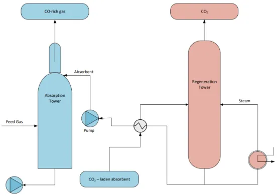
Asides from CO2, other by-products can be utilised to make useful products. TSIJ and Dow Benelux are currently building a pilot plant that utilises carbon monoxide (CO) from the waste gases of the blast furnaces to produce syngas. Syngas can be used to produce a range of products but this pilot plant will focus on naphtha, a hydrocarbon mixture that Dow use to make chemical products. TSIJ claims that they can supply around 5% of the current naphtha production by Dow. Producing naphtha is a higher value application than the production of electricity and the emissions of doing so would no longer be included within the steelmaking plant, an advantageous attribute for the steelmaker. Several other major European
steelmakers are also working on similar projects (De Ingenieur, 2018).
Steel recycling
TSIJ recycles approximately 1.4 Mt of steel, both internally and externally sourced, in 2015. Scrap steel is inputted in to the BOF alongside pig iron from the BF. The use of scrap steel significantly reduces CO2 emissions from production but is subject to significant constraints on availability and cost. EAFs can be run entirely on scrap steel and currently account for 30% of global steel production and so competition for material is rife (World Steel
Association, 2018). Hence, decarbonisation options with an EAF provide the opportunity to greatly increase the level of scrap steel used provided that there is sufficient availability.
Energy efficiency
TSIJ have an energy efficiency program entitled Trias Energetica which consists of three main goals:
1. Reduce unnecessary energy consumption, e.g. heat insulation, start-up/shut-down procedures, design innovation.
2. Use sustainable energy sources for necessary energy consumption, e.g. wind, solar, biomass.
3. When sustainable energy sources are not possible, utilise more efficient, less pollu-tant fossil fuel sources, e.g. natural gas instead of coal.
A combination of these energy efficiency measures have helped TSIJ improve their energy efficiency by 32% since 1989. This is illustrated in Figure 21 and compared to steel mills deemed ‘world class’ in terms of energy efficiency, showing that TSIJ is one of the most en-ergy efficient steel mills in the world (Jägers & Kiesewetter, 2018). However, further incre-mental energy efficiency measures are becoming more difficult and thus larger, step-change technological investments are required to improve energy efficiency further (Jägers & Kiesewetter, 2018).
Figure 21. Energy efficiency of TSIJ overall processes relative to 1989
4.2 Material, energy and CO
2flows
An overview of the material, energy and CO2 flows for the selected decarbonisation options are formed using a range of sources specifically for each technology. Details of use of hydro-gen in ULCORED are not available and hence will be stated as a hydro-general hydrohydro-gen direct re-duction (H-DR) option. Alongside these alternative technologies, the use of existing EAF technology alone is also a valid option and hence is included. An explanation of how the flows have been devised are provided one-by-one in this section. For all options, processes that are present in the current situation at TSIJ are scaled linearly to meet 1 Mt of crude steel production. See section 3.2 for an explanation of how these values were devised alongside the CO2 emission calculation methodology. All excess WAGs are assumed to be combusted in an on-site CHP plant with 40% efficiency and a 1:1 electricity-to-heat ratio. It is also as-sumed that in the absence of any process gases, they are substituted by natural gas. All op-tions are shown schematically in Figure 22 - Figure 28.
EAF
The flows of this option are based on (EIPPCB, 2013) in which it is assumed that the process is based entirely on scrap steel. Average values are taken for all flows.
TGR-BF
The flows from the TGR-BF unit are based on version 4 from (Danloy, van der Stel, &
Schmöle, 2008). It is assumed that an equal share of sinter and pellets is used, analogous to what is currently practiced at TSIJ. A modification is made in that 90% top gas recycling rate is assumed, in-line with the results in (Junjie, 2018). The remaining 10%, alongside the tail gas of the VPSA, have an energetic content that is assumed to be used for the preheating of the recycled top gas. The energy density of both streams are calculated based on the value per Nm3 from (Danloy, van der Stel, & Schmöle, 2008): 6.9 MJ/Nm3 for the 10% unrecycled top gas and 1.5 MJ/Nm3 for the tail gas of the VPSA.
HIsarna
There is a lack of specific data for the HIsarna option, hence, several assumptions were re-quired to be made. The iron ore requirement is assumed to be analogous to the other pro-cesses, in which little variation is present between options. The coal requirement is assumed to 80% of the stated typical blast furnace coal requirements (17 * 80% = 13.6 GJ/t HRC) from (Croezen & Korteland, 2010). The electricity demand is taken from X. The oxygen re-quirements are calculated by performing a basic mole balance calculation based on the equa-tion of C + O2 → CO2 assuming that the top gas is almost 100% CO2. Working backwards from the CO2 emissions arising from the HIsarna reactor, the oxygen requirements are calcu-lated assuming an oxygen density of 1.331 kg/Nm3. The electricity requirements are as-sumed to be in the same range as that in the TGR-BF. It is asas-sumed that 100% of the CO2 is captured.
ULCORED
A ULCORED reactor based on natural gas has been primarily based on a simplified version of (Sikstrom, 2013). Due to the absence of a coke plant for this option, coke breeze has been substituted for coal in the pellet plant. The DRI and scrap steel flow into the EAF has been based on (Daniels, 2002).
H-DR
The flows in this option have been based on (Hölling & Gellert, 2018). It has been assumed that all iron ore requirements are met with pellets (although it may be also possible to use sinter). The flows in the water electrolyser to produce the required volume of hydrogen have been devised from a basic mole balance calculation.