EHRA/HRS Expert Consensus on Catheter Ablation of Ventricular
Arrhythmias
Developed in a partnership with the European Heart Rhythm Association (EHRA), a Registered
Branch of the European Society of Cardiology (ESC), and the Heart Rhythm Society (HRS); in
collaboration with the American College of Cardiology (ACC) and the American Heart Association
(AHA)
Etienne M. Aliot, MD, FESC, FHRS,
1William G. Stevenson, MD, FHRS,
2Jesus Ma Almendral-Garrote, MD, PhD,
3Frank Bogun, MD,
4C. Hugh Calkins, MD, FHRS,
5Etienne Delacretaz, MD, FESC,
6Paolo Della Bella, MD, PhD, FESC,
7Gerhard Hindricks, MD, PhD,
8Pierre Jaïs, MD, PhD,
9Mark E. Josephson, MD,
10Josef Kautzner, MD, PhD,
11G. Neal Kay, MD,
12Karl-Heinz Kuck, MD, PhD, FESC, FHRS,
13Bruce B. Lerman, MD, FHRS,
14Francis Marchlinski, MD, FHRS,
15Vivek Reddy, MD,
16Martin-Jan Schalij, MD, PhD,
17Richard Schilling, MD,
18Kyoko Soejima, MD,
19and David Wilber, MD
201
CHU de Nancy, Hôpital de Brabois, Vandoeuvre-les-Nancy, France;2Brigham and Women’s Hospital, Boston, MA, USA; 3Hospital General Gregorio Maranon, Madrid, Spain;4University of Michigan Health System, Ann Arbor, MI, USA; 5Johns Hopkins Hospital, Baltimore, MD, USA;6University Hospital, Bern, Switzerland;7Universita degli Studi, Centro Cardiologico F. Monzino, Milan, Italy;8University of Leipzig, Heartcenter, Leipzig, Germany;9Hôpital du Haut Leveque, Bordeaux, France; 10Beth Israel Deaconess Medical Center, Boston, MA, USA;11Institute For Clinical And Experimental Medicine (Ikem), Prague, Czech Republic; 12University of Alabama, Birmingham, AL, USA;13Asklepios Hospital St Georg, Hamburg, Germany; 14Cornell University Medical Center, New York, NY, USA; 15University of Pennsylvania, Philadelphia, PA, USA; 16University of Miami, Miami, FL, USA;17Leiden University Medical Center, Leiden, The Netherlands; 18Barts and the London NHS Trust, UK;19University of Miami, Miami, FL, USA; and20Loyola University Medical Center, Maywood, IL, USA
Preamble
The purpose of this Consensus Statement is to provide a state-of-the-art review of the field of catheter ablation of ventricular tachycardia (VT), and to report the findings of a Task Force, convened by the European Heart Rhythm As-sociation (EHRA) and the Heart Rhythm Society (HRS) that was charged with defining the indications, techniques, and outcomes of this procedure. This statement summarizes the opinion of the Task Force members based on their own experience in treating patients, as well as a review of the literature. It is directed to all healthcare professionals who treat patients who are considered for catheter ablation of VT. This statement is not intended to recommend or pro-mote catheter ablation of VT. Rather, the ultimate judge-ment regarding care of a particular patient must be made by the healthcare provider and the patient with consideration of the individual patient characteristics that impact on risks and benefits of the therapy. In writing a ‘consensus’
docu-ment, it is recognized that consensus does not mean that there was complete agreement among all Task Force mem-bers. We identified those aspects of VT ablation for which a true ‘consensus’ could be identified. Surveys of the entire Task Force were used to identify these areas of consensus. For the purposes of this Consensus Document, we defined a consensus as 70% or greater agreement by the members of this task force. One objective of this document is to improve patient care by summarizing the foundation of knowledge for those involved with catheter ablation of VT. All mem-bers of the Task Force, as well as peer reviewers of the document, were asked to provide disclosure statements of all relationships that might be perceived as real or potential conflicts of interest. Disclosures for the members of the task force are given in the Appendix section.
TABLE OF CONTENTS
I. INTRODUCTION ...887 II. VENTRICULAR TACHYCARDIA:
DEFINITIONS, MECHANISMS, AND
RATIONALE FOR ABLATION...887 Endorsed by the Heart Rhythm Society, the European Heart Rhythm
Association, a registered branch of the European Society of Cardiology, the American Heart Association and the American College of Cardiology.
1547-5271/$ -see front matter © 2009 Heart Rhythm Society and the European Heart Rhythm Association, a registered branch of the European Society of Cardiology. Published by Elsevier, Inc. All rights reserved. doi:10.1016/j.hrthm.2009.04.030
III. INDICATIONS FOR CATHETER ABLATION
OF VENTRICULAR TACHYCARDIA...891
IV. TECHNICAL ASPECTS...891
V. VENTRICULAR TACHYCARDIA IN STRUCTURAL HEART DISEASE ...899
VI. ABLATION OUTCOMES AND CONSIDERATIONS IN SPECIFIC DISEASES ...908
VII. IDIOPATHIC VENTRICULAR TACHYCARDIAS ...913
VIII. TRAINING AND INSTITUTIONAL REQUIREMENTS AND COMPETENCIES ...916
IX. CLINICAL TRIAL CONSIDERATIONS...918
X. CONCLUSIONS...921 APPENDIX...922 REFERENCES ...923 FIGURES...889, 890, 900, 906, 909 TABLES...888, 891, 920
I. Introduction
Catheter ablation is now an important option to control recurrent ventricular tachycardias (VTs). The field has evolved rapidly and is a work in progress. Ablation is often a sole therapy of VT in patients without structural heart disease and is commonly combined with an implantable cardioverter-defibrillator (ICD) and/or antiarrhythmic ther-apy for scar-related VTs associated with structural heart disease. As the field progresses, it is important that the medical profession play a significant role in critically eval-uating therapies as they are introduced and evolve. Rigorous and expert analysis of the available data documenting indi-cations, techniques, benefits and risks, and outcomes can produce helpful guidance to improve the effectiveness of care, optimize patient outcomes, and identify areas for im-provement and future research.
II. Ventricular tachycardia: definitions,
mechanisms, and rationale for ablation
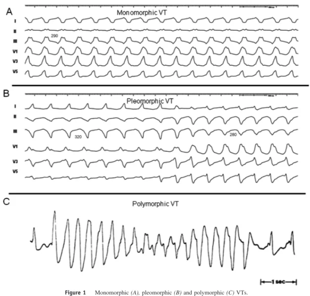
DefinitionsMany terms have entered clinical usage to describe observa-tions during mapping and ablation of VT. There has been substantial variation in the use of some terms by different investigators. The committee felt that these terms should be standardized to facilitate better understanding of methods, end-points, and outcomes across centres (Table 1 and Figure 1).1-4 Mechanisms and basis for catheter ablation of ventricular tachycardia
Monomorphic VT can occur in individuals with or without structural heart disease. The underlying heart disease and clinical characteristics of the VT often suggest a potential mechanism and origin. Ventricular tachycardias that are due to automaticity are expected to have a focal origin, making them susceptible to ablation with discrete radiofrequency (RF) lesions.5-12 Triggered activity or automaticity are likely causes of focal origin VTs, although small reentry circuits can often not be excluded. Idiopathic outflow tract
(OT)-VTs have a focal origin. Relatively large reentry cir-cuits are common in VT associated with ventricular scar, such as prior infarction, but VT may appear focal if the reentry circuit is small, or due to a focal endocardial break-through from an epicardial reentry circuit. Automaticity can occur in some patients with ventricular scars.
Triggered activity and automaticity
Triggered activity arises from oscillations in membrane potential during (early afterdepolarizations) or following (delayed afterdepolarizations) an action potential. Experi-mental evidence implicates early afterdepolarizations in the initiation of polymorphic tachycardias in the long QT syn-dromes.13 However, the mechanism of the premature
ven-tricular beats targeted for ablation in these syndromes is unknown.14
Delayed afterdepolarizations can be caused by intracel-lular calcium overload which activates the Na⫹/Ca2⫹ ex-changer resulting in the transient inward current Iti.1-4
Fac-tors that increase intracellular calcium include increases in heart rate,-adrenergic stimulation, and digitalis. -Adren-ergic effects are mediated through a cAMP-induced in-crease in intracellular calcium and are antagonized by aden-osine, which effects a decrease in cAMP. Termination of idiopathic right ventricular outflow tract (RVOT) tachycar-dias by an intravenous bolus of adenosine or infusion of calcium channel blockers, or by vagotonic manoeuvres is consistent with triggered activity as the likely mechanism for some of these tachycardias.3These tachycardias can be
difficult to induce at electrophysiology (EP) testing; rapid burst pacing and/or isoproterenol infusion is often required. Aminophylline, calcium infusion, and atropine may also be useful.15
Less commonly, focal VT may be due to automaticity that is provoked by adrenergic stimulation that is not trig-gered.1,15 This type of VT may become incessant under
stress or during isoproterenol administration, but cannot be initiated or terminated by programmed electrical stimula-tion; it can sometimes be suppressed by calcium channel blockers or-blockers. In contrast to its effects on triggered RVOT tachycardia, adenosine transiently suppresses the arrhythmia but does not terminate it.1,15Automaticity from
damaged Purkinje fibres has been suggested as a mechanism for some catecholamine-sensitive, focal origin VTs.16,17
Whether these VTs are due to abnormal automaticity, orig-inating from partially depolarized myocytes, as has been shown for VTs during the early phase of myocardial infarc-tion (MI), is not clear.
Although automaticity is often associated as a mecha-nism of VT in the absence of overt structural heart disease, disease processes that diminish cell-to-cell coupling are likely to facilitate automaticity.18,19 Automatic VTs can
occur in structural heart disease,17and automatic premature
beats may initiate reentrant VTs.
Scar-related reentry
The majority of sustained monomorphic VTs (SMVTs) in patients with structural heart disease are due to reentry
associated with areas of scar, designated as scar-related reentry (Table 1). Evidence supporting reentry includes initiation and termination by programmed stimulation (al-though this does not exclude triggered activity), demonstra-ble entrainment or resetting with fusion, and continuous electrical activity that cannot be dissociated from VT by extrastimuli. Myocardial scar is identified from: low-volt-age regions on ventricular voltlow-volt-age maps, areas with frac-tionated electrograms, unexcitability during pace mapping, evidence of scar on myocardial imaging, or from an area of known surgical incision. Prior MI is the most common
cause, but scar-related VT also occurs in other myocardial diseases including arrhythmogenic right ventricular cardio-myopathy (ARVC), sarcoidosis, Chagas’ disease, dilated cardiomyopathy, and after cardiac surgery for congenital heart disease (particularly Tetralogy of Fallot) or valve replacement.20-30
The substrate supporting scar-related reentry is charac-terized by (i) regions of slow conduction, (ii) unidirectional conduction block at some point in the reentry path that allows initiation of reentry, and (iii) areas of conduction block that often define parts of the reentry path.31-34
Ven-Table 1 Definitions
Clinical characteristics
Clinical ventricular tachycardia (VT): VT that has occurred spontaneously based on analysis of 12-lead ECG QRS morphology and rate. There are many potential problems and assumptions with this designation as it is applied to inducible VT in the electrophysiology laboratory (see Endpoints for ablation section).
Haemodynamically unstable VT causes haemodynamic compromise requiring prompt termination.
Idiopathic VT is a term that has been used to indicate VT that is known to occur in the absence of clinically apparent structural heart disease.
Idioventricular rhythm is three or more consecutive beats at a rate of⬍100/min that originate from the ventricles independent of atrial or AV nodal conduction.
Incessant VT is continuous sustained VT that recurs promptly despite repeated intervention for termination over several hours. Non-clinical VT is a term that has been used to indicate a VT induced by programmed ventricular stimulation that has not been
documented previously. This term is problematic because some VTs that have not been previously observed will occur spontaneously.262It is recommended that this term can be avoided. Induced VTs with a QRS morphology that has not been
previously observed should be referred to as ‘undocumented VT morphology’. Non-sustained VT terminates spontaneously within 30 s.
Presumptive clinical VT is similar to a spontaneous VT based on rate and ECG or electrogram data available from ICD interrogation, but without the 12-lead ECG documentation of either the induced or spontaneous VT.
Repetitive monomorphic VT: continuously repeating episodes of self-terminating non-sustained VT.378,462
Sustained VT: continuous VT forⱖ30 s or that requires an intervention for termination (such as cardioversion).
Ventricular tachycardia: a tachycardia (rate⬎100/min) with three or more consecutive beats that originates from the ventricles independent of atrial or AV nodal conduction.
VT storm is considered three or more separate episodes of sustained VT within 24 h, each requiring termination by an intervention.262,463
VT morphologies
Monomorphic VT has a similar QRS configuration from beat to beat (Figure 1A). Some variability in QRS morphology at initiation is not uncommon, followed by stabilization of the QRS morphology.
Multiple monomorphic VTs: refers to more than one morphologically distinct monomorphic VT, occurring as different episodes or induced at different times.
Polymorphic VT has a continuously changing QRS configuration from beat to beat indicating a changing ventricular activation sequence (Figure 1C).
Pleomorphic VT has more than one morphologically distinct QRS complex occurring during the same episode of VT, but the QRS is not continuously changing (Figure 1B).
Right and left bundle branch block-like—VT configurations: terms used to describe the dominant deflection in V1, with a dominant R-wave described as ‘right bundle branch block-like’ and a dominant S-wave as ‘left bundle branch block-like’ configurations. This terminology is potentially misleading as the VT may not show features characteristic of the same bundle branch block-like morphology in other leads.
Unmappable VT does not allow interrogation of multiple sites to define the activation sequence or perform entrainment mapping; this may be due to: haemodynamic intolerance that necessitates immediate VT termination, spontaneous or pacing-induced transition to other morphologies of VT, or repeated termination during mapping.
Ventricular flutter is a term that has been applied to rapid VT that has a sinusoidal QRS configuration that prevents identification of the QRS morphology. It is preferable to avoid this term, in favour of monomorphic VT with indeterminant QRS morphology.
Mechanisms
Scar-related reentry describes arrhythmias that have characteristics of reentry and originates from an area of myocardial scar
identified from electrogram characteristics or myocardial imaging. Large reentry circuits that can be defined over several centimetres are commonly referred to as ‘macroreentry’.
Focal VT has a point source of earliest ventricular activation with a spread of activation away in all directions from that site. The mechanism can be automaticity, triggered activity, or microreentry.
tricular tachycardia after MI has been extensively studied in canine models and in humans.35-41Reentry occurs through
surviving muscle bundles, commonly located in the suben-docardium, but that can also occur in the mid-myocardium and epicardium. There is evidence of ongoing ion channel remodelling within scar, at least early after MI, resulting in regional reductions in INa and ICa,42 although late after
infarction action potential characteristics of surviving myo-cytes can be near normal.35 Coupling between myocyte bundles and myocytes is reduced by increased collagen and connective tissue, diminished gap junction density, and al-terations in gap junction distribution, composition, and function.43Surviving fibres can be connected side to side in regions where the collagenous sheathes are interrupted, re-sulting in a zig-zag pattern of transverse conduction along a pathway lengthened by branching and merging bundles of surviving myocytes34,35,44,45The pattern of fibrosis may be important in determining the degree of conduction delay; patchy fibrosis between strands of surviving muscle pro-duces greater delay than diffuse fibrosis.31,46These aspects of scar remodelling contribute to the formation of channels
and regions where conduction time is prolonged, facilitating reentry.47
Unidirectional conduction block may occur after a prop-erly timed extra-beat and is probably functional rather than fixed in most instances (see below).38,48,49Regions of con-duction block can be anatomically fixed such that they are present during tachycardia and sinus rhythm; dense, non-excitable fibrosis or valve annuli create these types of ana-tomical boundaries for reentry (Figure 2).50-53 Alterna-tively, conduction block can be functional and present only during tachycardia when the refractory period of the tissue exceeds the tachycardia cycle length, or is maintained by collision of excitation waves (Figure 2D).33,38,48,49,54 Func-tional conduction block can occur in figure of eight type of reentry circuits.40,45,55,60
Many reentry circuits contain a protected isthmus or channel of variable length, isolated by arcs of conduction block.30,35,54-64Depolarization of the small mass of tissue in
a channel is not detectable in the body surface ECG; thus catheter-recorded electrograms in this region are manifest during ‘electrical diastole’ between QRS complexes. At the
exit from the channel, the wavefront propagates across the ventricles establishing the QRS complex. To return to the entrance to the channel, the reentry wavefront may propa-gate along the border of the scar in an outer loop or may propagate through the scar in an inner loop. Multiple po-tential loops may be present. There are a variety of popo-tential reentry circuit configurations and locations that vary from patient to patient.33,54,56-58 Often VT isthmus sites span a few centimetres at the border zone of scars.54,56,58,59Larger macroreentry circuits spanning several centimetres can also be encountered.54,57,58 In cardiomyopathies and inferior wall infarcts, reentry circuits are often located adjacent to a valve annulus, suggesting that the valve annulus often helps to define a reentry path.54,55,60,61,66
Multiple VT morphologies are usually inducible in the same patient, often related to multiple reentry circuits. Two different reentry circuits may share the same exit with functional block changing the QRS morphology, may have the same or similar common isthmus with a different exit, or may have two different isthmuses in different areas of the same scar or in different scars (Figure 2).55,56,58,62 The presence of multiple potential reentry circuit paths and the anatomic complexity of scars that support reentry
compli-cate mapping and ablation. It can be difficult to distinguish bystander regions that are not part of the reentry circuit from a critical isthmus.30,63A bystander region for one VT may participate in a different VT (Figure 2). Further complicat-ing assessment is the potential three-dimensional configu-ration of circuits, which can involve the endocardium, epi-cardium, or mid-myocardium.33,35,38,56
It is possible that other reentry mechanisms cause some VTs. Spiral wave reentry can be induced in excitable tissue in the absence of tissue discontinuities and could cause ventricular fibrillation (VF) or polymorphic VT (PMVT); anchoring to a discontinuity or region of slow conduction could theoretically cause monomorphic VT.34,64 Whether
this type of functional reentry causes VT in humans and whether it would be susceptible to ablation is not known.
Reentry in the Purkinje system
Reentry within the Purkinje fibres and the specialized con-duction system causes ⬃5% of all SMVTs encountered in patients undergoing catheter ablation. Macroreentry through the bundle branches occurs in patients with slowed conduc-tion through the His-Purkinje system and is usually associ-ated with severe left ventricular (LV) dysfunction due to
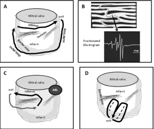
Figure 2 Theoretical reentry circuits related to an inferior wall infarct scar are shown. (A) A large inferior wall infarct designated by the dashed line and shaded border zone. Areas of dense fibrosis define an isthmus along the mitral annulus. A large reentry circuit uses this isthmus and exits at the lateral aspect of the scar. An outer loop propagates along the border to re-enter the isthmus at the medial aspect. Note that this circuit could potentially revolve in the opposite direction as well (not shown) producing VT with a different QRS morphology. Bystander regions are present as well. (B) The anatomic basis of slow conduction that facilitates reentry is shown. Fibrosis (dark bands) separates muscle bundles creates circuitous paths for conduction. Electrograms from these regions have a fractionated appearance indicating asynchronous activation of myocyte bundles. (C) The effect of ablation (Abl) at the exit for the VT. VT⫺1 is interrupted but other potential reentry paths are present that can allow other VTs. (D) A functionally defined figure-eight type of reentry circuit, in which the central isthmus is defined by functional block (dashed lines).
dilated cardiomyopathy, valvular heart disease, and less often ischaemic heart disease (see below).65,67,68,70
Left ventricular intrafascicular verapamil-sensitive VT occurs in patients without structural heart disease. The mechanism is reentry that appears to involve a portion of the LV Purkinje fibres, most often in the region of the left posterior fascicle, giving rise to a characteristic right bundle branch block (RBBB) superior axis QRS configuration and a QRS duration that is only slightly prolonged.69,70 Electrophysiological basis for catheter ablation The mechanism of VT is a key determinant for selection of mapping strategies to identify ablation target sites. For idiopathic VT, the focal origin or critical portion of the reentry path is usually contained in a very small area such that discrete lesions can abolish VT; therefore, mapping targets a precise region. For scar-related VTs, ablation is aimed at transecting the critical VT isthmus. Ventricular tachycardia isthmuses may be narrow, allowing a discrete lesion to abolish VT, or broad, requiring larger ablation areas. In addition, in patients with unmappable VTs and multiple VTs, larger ablation areas targeting putative criti-cal reentry sites, often in or near the border zone of scars, are often employed. In post-MI VT, most reentry circuit isthmuses can be transected using an endocardial ap-proach.50,52,54,57,59,62,71-73However, critical reentry circuit sites are intramural or subepicardial in some patients; these locations are common in some cardiomypathies.71,74,75
In Purkinje reentry VT, specialized conduction fibres that are part of the reentry path are targeted for ablation.17,65,67,68
III. Indications for catheter ablation of
ventricular tachycardia
Selection of catheter ablation for an individual patient should consider risks and benefits that are determined by patient characteristics, as well as the availability of appro-priate facilities with technical expertise. In patients with structural heart disease, episodes of sustained VT are a marker for increased mortality and reduce quality of life in patients who have implanted defibrillators and structural heart disease.76-80 Antiarrhythmic medications can reduce the frequency of ICD therapies, but have disappointing efficacy and side effects.81-83Advances in technology and understanding of VT substrates now allow ablation of mul-tiple and unstable VTs with acceptable safety and efficacy, even in patients with advanced heart disease. In the past, ablation was often not considered until pharmacological options had been exhausted, often after the patient had suffered substantial morbidity from recurrent episodes of VT and ICD shocks. There was consensus among the task force members that catheter ablation for VT should gener-ally be considered early in the treatment of patients with recurrent VT. General recommendations for the use of cath-eter ablation are summarized in Table 2. More detailed information regarding risks and benefits for specific types of VT and in specific types of heart disease is provided in sections below. It should be recognized that the database for
these consensus recommendations consists largely of un-controlled trials and single-centre reports as summarized in the discussion of individual diseases below.
IV. Technical aspects
Technologies for mapping and ablation
Technological advances have been critical to the develop-ment of the field and will continue to play an important role in improving outcomes. The evaluation of new technologies
Table 2 Indications for catheter ablation of ventricular tachycardia
Patients with structural heart disease (including prior MI,
dilated cardiomyopathy, ARVC/D) Catheter ablation of VT is recommended
1. for symptomatic sustained monomorphic VT (SMVT), including VT terminated by an ICD, that recurs despite antiarrhythmic drug therapy or when antiarrhythmic drugs are not tolerated or not desired;*
2. for control of incessant SMVT or VT storm that is not due to a transient reversible cause;
3. for patients with frequent PVCs, NSVTs, or VT that is presumed to cause ventricular dysfunction;
4. for bundle branch reentrant or interfascicular VTs; 5. for recurrent sustained polymorphic VT and VF that is
refractory to antiarrhythmic therapy when there is a suspected trigger that can be targeted for ablation. Catheter ablation should be considered
1. in patients who have one or more episodes of SMVT despite therapy with one of more Class I or III antiarrhythmic drugs;* 2. in patients with recurrent SMVT due to prior MI who have LV
ejection fraction⬎0.30 and expectation for 1 year of survival, and is an acceptable alternative to amiodarone therapy;* 3. in patients with haemodynamically tolerated SMVT due to prior
MI who have reasonably preserved LV ejection fraction (⬎0.35) even if they have not failed antiarrhythmic drug therapy.*
Patients without structural heart disease
Catheter ablation of VT is recommended for patients with idiopathic VT
1. for monomorphic VT that is causing severe symptoms. 2. for monomorphic VT when antiarrhythmic drugs are not
effective, not tolerated, or not desired.
3. for recurrent sustained polymorphic VT and VF (electrical storm) that is refractory to antiarrhythmic therapy when there is a suspected trigger that can be targeted for ablation.
VT catheter ablation is contra-indicated
1. in the presence of a mobile ventricular thrombus (epicardial ablation may be considered);
2. for asymptomatic PVCs and/or NSVT that are not suspected of causing or contributing to ventricular dysfunction; 3. for VT due to transient, reversible causes, such as acute
ischaemia, hyperkalaemia, or drug-induced torsade de pointes.
ARVC/D, arrhythmogenic right ventricular cardiomyopathy/dysplasia; ICD, implantable cardioverter defibrillator; MI, myocardial infarction; VT, ventricular tachycardia; VF, ventricular fibrillation.
*This recommendation for ablation stands regardless of whether VT is stable or unstable, or multiple VTs are present.
has generally been based on uncontrolled series. There is limited head-to-head comparison of different technologies. Although new technologies generally increase the cost of a procedure when they are introduced, the costs may be jus-tified if they improve outcomes.
The process of evaluation and adoption of new technol-ogies for clinical practice varies from country to country. In this document, the assessment of technologies is based on review of the literature and consensus of the task force. Individual technologies may not have been approved spe-cifically for catheter ablation of VT. It is important for the electrophysiologist performing these procedures to recog-nize the value and limitations of each mapping system for their effective use. As the field continues to evolve, adop-tion of new technologies should be based on well-designed clinical trials.
Mapping systems
Mapping systems that create chamber geometry and display the ablation catheter position are often helpful in ablation of VT in structural heart disease and can be useful in selected patients with idiopathic VT.
Electroanatomic mapping systems
Electroanatomic mapping (EAM) refers to point by point contact mapping combined with the ability to display the location of each mapping point in three-dimensional space. This provides the opportunity to record intracardiac electri-cal activation in relation to anatomielectri-cal location in a cardiac chamber of interest. Electroanatomic mapping systems in-tegrate three main functions: (i) non-fluoroscopic localiza-tion of the ablalocaliza-tion catheter within the heart; (ii) display of electrogram characteristics, most commonly activation time or voltage, in relation to anatomic position; and (iii) inte-gration of electroanatomic information with three-dimen-sional images of the heart obtained from point by point sampling, intracardiac ultrasound, computed tomography (CT), or magnetic resonance imaging (MRI).
In patients with scar-related VTs, EAM systems are useful. In patients with idiopathic VTs, EAM systems can be useful, but are not required and are utilized by approxi-mately half of the task force members.
One system utilizes low-level electromagnetic fields em-anating from three separate coils beneath the patient that are measured from a location sensor embedded in the tip of the mapping catheter.84This allows a three-dimensional recon-struction of the chamber of interest and colour-coded dis-play of various electrophysiological parameters for endo-cardial or epiendo-cardial mapping54,73,85-87 An alternative technology determines electrode position based on the mea-surement of a high-frequency current emitted by three pairs of orthogonally placed skin patches.62,88,89Recently, intra-cardiac echocardiography (ICE) has been incorporated into EAM.90The ICE probe, equipped with a location sensor and tracked by the mapping system, allows reconstruction of a three-dimensional shell of the chambers of interest before
mapping and may help define irregular anatomic features, such as papillary muscles.90
The ability to continuously monitor catheter position without fluoroscopy is expected to reduce fluoroscopy ex-posure. Electroanatomic mapping systems allow activation mapping that has been used to support catheter ablation of idiopathic focal and reentrant VTs originating in the RV or LV, and/or aortic cusps.91-94Electroanatomic mapping sys-tems are used extensively in patients with VTs due to structural heart disease.28,53,54,59,73,85-87,95-107Often the sys-tem is used without performing detailed activation maps, but to obtain an anatomical shell and enable annotation of mapping points of interest, as may be determined based on entrainment mapping or pace mapping. Combining anatomy with plots of electrogram amplitude in ‘voltage maps’ helps identify areas of ventricular scar, an innovation that was important for the development of substrate mapping (see below).73
There are a number of limitations of these systems. Cardiac and respiratory motion reduce anatomic accuracy. Patient movement relative to the location signal or reference sources invalidates the anatomic maps and can be a major problem when procedures are done with sedation rather than general anaesthesia. Algorithms for anatomic reconstruction differ between systems and likely have different weak-nesses. Data are acquired point by point, such that a stable tachycardia or haemodynamic support is usually required for the definition of a complete activation sequence. Point by point mapping is a tedious process that requires consid-erable skill with catheter manipulation. Incorporation of multiple mapping catheters and electrodes may facilitate spatial sampling.108,109
Multielectrode arrays
Mapping systems that allow for multielectrode mapping are an alternative to point by point sampling that can facilitate reconstruction of the activation sequence and identification of abnormal areas. There are currently two different strate-gies that allow multielectrode mapping.
A basket-shaped catheter composed of multiple thin splines, each of which has multiple electrodes distributed throughout the length of the spline that can be advanced through a long introducer sheath into the ventricle, has been described.110,111In addition to recording the activation
se-quence, pace mapping can be performed through the elec-trodes that are in contact with the endocardium.112 Limita-tions include mechanical trauma that can terminate VT or induce ectopic beats, incomplete, irregular spatial sampling because the splines do not deploy uniformly and some of the electrodes are often not in contact with myocardium. The splines may interfere with manipulation of an ablation cath-eter. The potential for clots to form on the splines necessi-tates careful attention to anticoagulation during the proce-dure. Small case series and anecdotal reports describe their use to determine ventricular activation sequence during si-nus rhythm and during VT in patients with scar-related VTs110,111 and to guide ablation of idiopathic RVOT
VT.112,113Other multielectrode catheters are available, but have not been evaluated for guiding VT ablation.108,109 These multielectrode arrays (MEAs) that allow contact mapping can be useful in selected patients, but are generally not used by the task force members.
A non-contact mapping system consists of a catheter with an MEA of 64 unipolar electrodes over an inflatable balloon.114-116 The MEA measures the potential generated by far-field electrograms and also detects the location of a roving mapping catheter. Three-dimensional endocardial geometry is created by dragging the roving catheter around the ventricle. From the sampled far-field potentials and the measured distance between the array and the endocardium, an ‘inverse solution’ is calculated for the potentials at ⬎3000 points on the endocardial surface to create ‘virtual unipolar electrograms’. The virtual electrograms agree with electrograms obtained by contact mapping provided that the endocardial surface of interest is within 4 cm from the centre of the MEA balloon.114,115,117
The system is best suited for activation mapping. In scar-related VTs, an endocardial exit region is identified in ⬎90% of cases, and a portion of the diastolic pathway can be delineated in some.116,118,119Because single beat activa-tion can be assessed, data can be acquired from non-sus-tained, poorly tolerated, or pleomorphic VTs.
An understanding of the limitations is important to avoid errors in mapping and interpretation of mapping data. Care has to be taken to confirm that the virtual electrogram is related to local activation and not baseline drift or repolar-ization. Because accuracy decreases as the distance between the MEA and endocardium increases, it should be used with caution in large ventricles. Methods to detect scar based on characteristics of virtual electrograms are under investiga-tion, but may be more difficult to achieve than with contact mapping.117,120-122Displacement of the MEA after creation of endocardial geometry invalidates subsequent mapping data. At present, detection and display of activation from two adjacent structures, such as the papillary muscle and subjacent myocardium, is problematic. The potential for thrombus formation on the MEA requires careful attention to anticoagulation, maintaining an activated clotting time (ACT)⬎300 s is recommended. The mapping sheath is 9F in diameter; femoral haematomas and pseudoaneurysms are the most frequently encountered complications.
Single-centre case series and case reports have shown that the system can be used to guide catheter ablation of VT in patients with idiopathic VT123-125and scar-related VTs due to arrhythmogenic right ventricular dysplasia (ARVD),126congenital heart disease,127cardiomyopathy, and MI.116,118,119,128,129
Robotic navigation
Catheter-based ablation of VT places significant demands on the skill and experience of the electrophysiologist. Re-mote, robotic catheter manipulation seeks to achieve precise and stable catheter navigation, reduced radiation exposure for patient and operator, and shorter procedure times. This
concept is appealing for the operator, for whom it may reduce radiation exposure and the chronic physical stress related to prolonged use of protective lead aprons. Two technologies are available, a robotic controlled sheath sys-tem130,131 and a magnetic navigation system that is com-bined with an EAM system.132-134Neither is FDA-approved for ablation of VT. The large diameter and relatively short reach of the robotically controlled sheath limit applicability for ventricular mapping and no clinical experience with VT ablation has been published. Small case series reporting the use of the magnetic navigation system indicate that point by point mapping can be accomplished with very short fluo-roscopy exposure times.113,135-137At present, studies are not available to demonstrate that either of these systems short-ens procedure times or improves efficacy or safety of VT ablation. Such studies are needed to determine their role in catheter ablation of VT and to justify their expense. The present reported experience is not sufficient to form a conclu-sion as to the utility of these technologies for VT ablation. Imaging
An understanding of anatomy is important for mapping and ablation. There is increasing interest in cardiac imaging to identify anatomic correlates and obstacles to ablation of VT. There are no trial data to show that sophisticated imaging improves ablation outcomes, but there is substantial expe-rience with pre- and post-procedure echocardiographic im-aging, which is widely accepted in clinical practice.
Pre-procedural imaging is used to identify ventricular thrombi that could increase the risk of endocardial mapping (see below), and identify regions of wall motion abnormal-ities that may contain the potential VT substrate. Because defining the presence and severity of underlying heart dis-ease is an important part of the clinical evaluation of any patient with ventricular arrhythmias, almost all patients should have some type of pre-procedural imaging, such as echocardiography, ventriculography, nuclear imaging, and/or MRI or CT imaging.
When scar-related VT is suspected, imaging can be used to characterize the location/extent of the myocardial scar that is likely to contain the VT substrate.97,138-140Magnetic resonance imaging using delayed Gd enhancement pulse sequences can be used to identify scar with good spatial resolution. Magnetic resonance imaging is limited in the VT population because many patients have implanted perma-nent pacemakers or defibrillators. Many institutions prohibit the use of MRI in these patients, although feasibility of imaging with a 1.5 T magnet in patients with pacemakers or defibrillators (after changing the pacing mode to either ‘de-mand’ only or ‘asynchronous’ for pacemaker-dependent patients, and disabling magnet response and tachyarrhyth-mia functions) has been demonstrated.141-143 ‘Delayed en-hancement’ CT imaging has been investigated for visualiz-ing scarred myocardium, but the reproducibility and true sensitivity of this imaging modality are still unclear.144,145 Positron emission tomography–CT (PET-CT) can provide scar location information, albeit with less spatial accuracy
than MRI.144,145It is likely that further advances in imaging technologies will allow more precise imaging of myocardial scar in the future and further studies will be required to determine their utility for facilitating VT ablation.146,147
Intracardiac echocardiography is increasingly employed during procedures. It can be used to define three-dimen-sional ventricular chamber geometries and to observe con-tact between the catheter tip and underlying tissue that can be helpful during ablation on irregular structures such as papillary muscles.148-150Intracardiac echocardiography has been used to visualize the proximity of the ablation catheter tip to an adjacent coronary artery when ablating in the left ventricular outflow tract (LVOT) or aortic valve cusps, but requires skill and experience in obtaining and interpreting ICE images.151,152Coronary angiography to allow fluoro-scopic visualization of coronary anatomy is presently more commonly employed for this purpose.
Another emerging intra-procedural imaging strategy is the incorporation of pre-acquired volumetric MRI, CT, or PET-CT images into mapping systems to help to detect the arrhythmia substrate as well as anatomic obstacles to abla-tion, such as epicardial fat.145,147,153 The clinical value of these methods has not yet been demonstrated.
Post-procedural imaging is indicated when there is hae-modynamic deterioration or instability. Most commonly, imaging with transthoracic echocardiography is performed to assess the presence of pericardial effusion and tampon-ade, valve injury, or deterioration of ventricular function. Energy sources for ablation
Radiofrequency energy is most commonly used for ablation and is relatively simple and effective. Ablation of idiopathic VTs can often be accomplished with relatively small lesions created by RF applied to a solid electrode 4 or 5 mm in length. Ablation of scar-related VTs can require ablation of large areas and regions deep to the endocardium that is facilitated by the use of larger electrodes or irrigated elec-trodes. There is consensus that irrigated RF electrodes are preferred for ablation of scar-related VT. There are no randomized trials comparing different RF ablation methods for VT ablation. There is limited experience with other energy sources.
Standard radiofrequency ablation
Thermal injury produced by RF ablation is due to resistive heating of tissue with some conductive heating of the sur-rounding tissue.154-156 Permanent tissue injury occurs at temperatures exceeding 49°C. The RF electrode heats as a consequence of its contact with the tissue. Heating is limited by coagulation of proteins on the electrode that occurs at electrode temperatures exceeding 70°C. Circulating blood cools the electrode such that measured catheter electrode temperature is less than tissue temperature. Tissue heating is indicated by the increase in electrode temperature and fall in measured impedance during ablation.
For endocardial ablation of idiopathic VT, standard solid 4 or 5 mm electrode RF ablation catheters are usually
adequate. In addition to RF power and duration, which are controlled by the operator, the effectiveness of RF lesion creation depends on electrode–tissue contact and the extent of cooling from circulating blood flow which are variable and not known by the operator.154-156The optimal method
of energy application has not been defined and a variety of different approaches to energy titration can be successful. Energy applications should be titrated to that required to eliminate the arrhythmia and to avoid excessive tissue dam-age. Power of 30 –50 W is typically applied in the temper-ature control mode and titrated to an electrode tempertemper-ature of 55–70°C or an impedance fall of 10 –15 ohm. Careful attention to temperature, impedance, and power is impor-tant. Brisk heating at low power (e.g.⬍15 W) may indicate the location of the electrode in a low flow area and limited lesion creation, despite electrode heating. A brisk fall in impedance of ⬎18 ohm may indicate substantial tissue heating and may warrant a reduction in power to avoid steam pops (see below), even though measured temperature is⬍60°C.155,156
Compared with standard solid 4 or 5 mm length elec-trodes, increasing ablation electrode size (typically to 8 or 10 mm) allows greater energy delivery because the greater surface area of the electrode increases electrode cooling from circulating blood.155,156 Although this is relatively simple and avoids the need for irrigation pumps, there are disadvantages of large electrodes. Greater power is required for lesion creation. There is a greater disparity in tempera-tures across the surface of the large electrode such that hot regions can lead to coagulum formation despite relatively low temperatures recorded from the electrode. Increasing the size of the electrode reduces the spatial resolution of mapping.
Irrigated radiofrequency ablation
Irrigation of the ablation electrode allows more power to be applied before temperature increases to the point of coagu-lum formation, increasing the size of RF lesions that can be created and facilitating interruption of scar-related ventric-ular reentry.157Two different types of electrode irrigation are available. An internal irrigation catheter circulates 5% dextrose solution at room temperature in a closed loop through the tip electrode. Open irrigation catheters infuse saline that emerges through pores in the ablation electrode, cooling the electrode and providing some cooling of the tissue– electrode interface. There are no trials directly com-paring open vs. closed irrigation for RF ablation of VT. In experimental preparations, external irrigation has a lower risk of coagulum and thrombus formation, possibly due to more effective electrode–tissue interface cooling, when compared with internal irrigation.158A low risk of
coagu-lum formation with open irrigation is supported by the absence of thromboembolic complications in three multi-centre trials involving 353 patients.102,105,106
External irrigation does result in intravascular saline ad-ministration, amounting to a median of 1 L of saline in a recent trial,105which can potentially cause pulmonary
oe-dema. Careful monitoring of fluid balance is required and a urinary catheter and diuretic administration may be needed during the procedure. Internal irrigation catheters or large tip catheters should be considered if intravascular volume administration will be difficult to manage, as in patients with renal failure and/or severe heart failure.
Electrode irrigation increases the disparity between tissue temperatures and temperatures recorded from within the elec-trode.158If tissue temperatures exceed 100°C, an explosion of
steam within the tissue can occur often with an audible ‘pop’.158These pops can cause perforation.159This risk may be greater in thin-walled structures such as the RV and atria. During ablation in areas of scar, pops are usually not associated with perforation.159 Cardiac tamponade has been reported in 1% of patients in multicentre trials.102,105,106,160 In animal
models of atrial ablation, pops are more likely to occur when electrode temperature exceeds 40°C, particularly if power is ⬎40 W, and are often associated with only a small impedance rise, dislocation of the catheter, and a sudden drop in electrode temperature.161,162 It has also been suggested that the risk of perforation is greater if the electrode is oriented perpendicular to the tissue, rather than when it is parallel in orientation. In a retrospective study of RF ablation with external irrigation at 30 mL/min for VT ablation, steam pops occurred in 1.5% of 4107 RF ablation lesions.159Tamponade occurred following 1 of the
62 pops (2%); this RF application was at the free wall of the RV. Applications with steam pops had greater impedance falls (22⫾ 7 vs. 18 ⫾ 8 ohm) and greater maximum power (45 ⫾ 5 vs. 43⫾ 6 W), but did not differ in maximum catheter tip temperature (40 ⫾ 4°C in both groups). The magnitude of decrease in impedance during RF was the best predictor of a pop, with 80% of pops occurring after impedance had de-creased by⬎18 ohm.
The optimal parameters to guide power titration for irri-gated RF ablation are not completely defined. The greatest experience is with the 3.5 mm electrode with external irrigation at 10 –25 mL/ min for power up to 30 W and 30 mL/min for power of ⬎30 W. For endocardial ablation, initiation of RF current at 30 –35 W and increasing power to achieve an im-pedance fall of 10 –15 ohm while maintaining electrode tem-perature ⬍40–45°C is reasonable. The method employed should also consider the risks of ablation at the site. Lower power should be considered at sites where perforation is a risk, such as the free wall of the RV and within venous structures or in the great vessels.163,164 Other irrigated RF systems are in development, and specific operating parameters are likely to vary with a particular system.
Irrigation may be especially important for epicardial RF ablation.86,164-166Although the risk of embolism due to char formation does not exist for epicardial ablation, the absence of electrode cooling from circulating blood markedly limits energy delivery. To increase the depth of epicardial lesion formation, irrigation is necessary. Internally irrigated catheters can be effective. External irrigation infuses saline into the pericardium, necessitating aspiration during the procedure (see below). The optimal infusion rates for epicardial irrigated
ab-lation have not yet been defined, but successful abab-lation has been performed using irrigation at rates ranging from 2 to 30 cc/min. Irrigation is not needed during mapping.
Irrigated RF ablation has been reported in four multi-centre trials and is preferred for ablation of scar-related VT.86,102,105,106,160Some task force members prefer exter-nal irrigation, with careful power limitation and titration, for ablation of LV idiopathic VT in the hope of reducing risk of thrombus, although this benefit is not proven.
Other energy sources
Cryoablation catheters are available for clinical use, but there is no compelling data that these catheters improve lesion depth over irrigated RF ablation catheters. Animal data suggest that coronary artery injury is less likely with cryoablation than RF ablation when a coronary artery is close to the ablation target.167,168Feasibility of cryoablation
has been demonstrated in small case series and reports in selected clinical situations such as during epicardial ablation near a coronary artery or during ablation from within a coronary vein (which is typically near a coronary artery) and in children.164,169
Inability to create a sufficiently deep lesion to ablate VT is an important cause of ablation failure and can occur when critical portions of the reentry circuit are intramural or epicardial, when epicardial access cannot be achieved. An-imal studies have shown that laser, ultrasound, microwave, or intramural irrigated needle RF ablation can produce deep lesions (and the first three have been employed for surgical ablation of VT), but they are not clinically available for catheter ablation.170-175
Anticoagulation
Intravascular insertion and manipulation of catheters, cre-ation of ablcre-ation lesions, activcre-ation of coagulcre-ation factors, and potential disruption of atherosclerotic plaques contrib-ute to a risk of thromboembolism during and after catheter ablation.176,177The risk likely varies with the type and site of ablation, and patient factors that influence the tendency for thromboembolism. Patients with structural heart disease undergoing left heart catheterization have a risk of stroke or thromboembolism of⬃1%.72,105,119,160,178-186There are no data comparing different approaches to anticoagulation be-fore, during, or after the procedure. Antithrombotic mea-sures are recommended for all procedures involving left heart catheterization.
Recommendations for anticoagulation
The guidelines for anticoagulation management should be followed if a patient has atrial fibrillation and cardioversion may occur during the ablation procedure.
Right heart procedures that do not involve placement of a catheter into the left ventricle or atrium
During the procedure, systemic anticoagulation with hepa-rin is not necessary unless other factors are present that increase the risk for thromboembolic complications. Some laboratories routinely anticoagulate with heparin due to
con-cern for deep venous thrombosis and pulmonary emboli. Anticoagulation during the procedure may be considered, particularly for long procedures, when multiple venous catheters or when extensive ablation is required. Anticoag-ulation is warranted for patients with a history of prior venous thromboemboli, and/or who have known risk factors for thrombosis (e.g. Factor V Leiden) or have right to left intracardiac shunts that pose a risk of paradoxical embolism. Following the procedure, long-term anticoagulation is not required. Some centres administer aspirin 75–325 mg daily for 3–12 weeks.
Left heart procedures in the absence of structural heart disease
Anticoagulation therapy prior to the intervention is not required. During the procedure, systemic anticoagulation with intravenous heparin is recommended as for patients with structural heart disease. Ventricular tachycardia in these patients is usually ablated with a small number of focal lesions. After ablation, anticoagulation is not required. Some laboratories administer aspirin 75–325 mg for 4 – 8 weeks. Anticoagulation with warfarin may be considered for patients who receive extensive areas of ablation or who are at increased risk of thromboemboli.
Left heart procedures in patients with structural heart disease
Imaging to assess the presence of an LV thrombus is war-ranted prior to endocardial LV mapping. A mobile LV thrombus is a contraindication to LV endocardial mapping and ablation. Evidence of laminated thrombus is not a con-traindication to ablation; some laboratories prefer to antico-agulate with warfarin for 4 – 6 weeks prior to elective abla-tion when laminated thrombus is present. Anticoagulaabla-tion therapy is not generally necessary prior to the ablation procedure, but is often warranted for other indications in this patient population. Anticoagulation with warfarin may be interrupted 3–5 days before the procedure. Bridging therapy with heparin or low-molecular-weight heparin is dictated by other indications for anticoagulation.
Peri-procedure anticoagulation. After sheath insertion, sys-temic anticoagulation is warranted. Anticoagulation regi-mens differ among centres. Some do not administer heparin until it is determined that the aorta can be navigated with the ablation catheter, to preserve the option of performing trans-septal access prior to anticoagulation if vascular access is difficult. The potential use of percutaneous pericardial cess is also a consideration (see section on pericardial ac-cess). For adults, iv heparin is commonly administered as an initial bolus (empirical dose 5000 –10 000 U or 50 –100 U/kg) followed by a continuous infusion or intermittent boluses (usually 1000 –1500 U/h) to maintain an ACT level of ⱖ250 s with periodic measurement. Greater degrees of anticoagulation may be considered if long vascular sheaths are inserted into the ventricle by retrograde aortic or trans-septal approaches. Some electrode arrays that may be
thrombogenic require an ACT ⬎300 s. Anticoagulation is not needed for epicardial mapping and ablation (see below). Immediate post-procedure anticoagulation. At the comple-tion of the procedure, anticoagulacomple-tion with heparin or low molecular weight heparin may be instituted 4 – 6 h after haemostasis is achieved and continued for 12– 48 h or until the target INR is reached when warfarin is administered. Follow-up anticoagulation. During initial follow-up, antico-agulation is recommended with aspirin (75–325 mg daily) or warfarin for 6 –12 weeks. Following extensive ablation over large areas (e.g. several centimetres), anticoagulation with warfarin rather than aspirin is reasonable. Determina-tion of the anticoagulaDetermina-tion regimen should consider the extent of ablation, patient factors that influence the risk of thromboembolism, and the risks of anticoagulation. Antico-agulation regimens have not been tested in trials and these regiments are based on consensus. Some centres administer warfarin when LV function is severely depressed. Antico-agulation is not required if only epicardial ablation is performed.
Sedation and analgesia
Mapping and ablation procedures are performed with vari-able degrees of sedation and analgesia, which depend upon the extent of the procedure and the condition and charac-teristics of the patient. The purpose of sedation is to mini-mize anxiety and awareness and to relieve any pain caused by the procedure. The depth of sedation required ranges from minimal to deep and may include general anaesthesia. Assessment of the risks for sedation and anaesthesia must be performed prior to the procedure in order to preemptively plan for patient needs so that the progress of the case is unimpeded. Consultation with an anaesthesiologist is war-ranted for high-risk patients or those who are likely to require deep sedation and/or general anaesthesia so that haemodynamic stability and respiratory function are main-tained at all times. Sedation/analgesia needs to be adminis-tered by trained individuals with concomitant monitoring of heart rate, blood pressure, and oxygen saturation.188,189 Capnography can be useful because it provides an indica-tion of respiraindica-tion and cardiac funcindica-tion.188-190 Respiratory arrest may escape detection for 30 s or more when only arterial O2saturation is monitored.
The level of training required to safely administer intrave-nous sedation and analgesia has been outlined by the American Society of Anesthesiologists.188Personnel must also meet in-stitutional requirements that vary among centres.
Either conscious sedation or general anaesthesia may be used. The best sedation strategy for an individual patient is dependent upon patient age, associated co-morbidities, and targeted arrhythmias. In adults, short-acting benzodiaz-epines and opioid analgesics are often sufficient to achieve the level of sedation/analgesia necessary to perform a map-ping and ablation procedure. Supplementation with short-acting intravenous general anaesthetic agents such as
propo-fol, ketamine, or etomidate may also be helpful. General anaesthesia provides more complete relief of discomfort and has the advantage of avoiding patient movement, thereby facilitating the process of vascular access, epicardial access, and catheter manipulation and ablation. Manipulation of the ventilator cycle may also help to minimize catheter move-ment during ablation. Placemove-ment of an oral airway by a trained anaesthesiologist or supervised registered nurse can also be helpful in reducing respiratory motion in sedated patients.
General anaesthesia is usually required for ablation pro-cedures in children. It is also a safe alternative in adults at risk for airway obstruction, other respiratory compromise and haemodynamic instability, or in high-risk patients with other major co-morbidities. A major disadvantage of gen-eral anaesthesia is the potential for suppressing VT induc-ibility. It is desirable to avoid general anaesthesia and deeper levels of sedation in patients with catecholamine-sensitive VTs, particularly if VT was not inducible at a prior procedure. In children, propofol and isofurane do not inter-fere with inducibility of common supraventricular reentrant arrhythmias.191,192One study found no impact of enflurane on VT inducibility in patients with structural heart dis-ease.193Halothane decreased inducibility of VT in a post-infarction dog model.194 General anaesthesia may cause vasodilation and impair reflex responses to hypotension during induced VT, although this can often be countered with volume administration and vasopressors. If general anaesthesia is used during epicardial mapping and ablation procedures, paralytic agents should be avoided as these may prevent identification of the phrenic nerve by high output pacing.
As an alternative to general anaesthesia throughout the procedure, a deeper level of sedation can be achieved as needed with a drug such as propofol, when sudden move-ments of the patient need to be prevented in critical situa-tions (epicardial puncture, for example). If short-acting agents are used, the depth of sedation can be reduced when needed to facilitate initiation of VT.
Antiarrhythmic drug management in patients undergoing ablation
Most patients who undergo catheter ablation of VT or VF will have failed prior antiarrhythmic drug therapy because of either drug inefficacy or intolerance. Since catheter ab-lation of idiopathic VT in the absence of structural heart disease is greatly facilitated by activation mapping during spontaneous or induced VT, antiarrhythmic drugs (includ-ing -blockers) should be discontinued for 4–5 half-lives before the procedure. For patients with poorly tolerated VT, hospitalization may be required for drug discontinuation. After ablation of idiopathic VT, most patients can be dis-charged without antiarrhythmic drugs, although it may be prudent to gradually taper -blockers.
In contrast to patients with idiopathic VT, many of those with VT related to significant structural heart disease have received prior treatment with Class III antiarrhythmic drugs
such as sotalol or amiodarone.82,83,101,105,160,195 If VT is incessant, catheter ablation is usually performed on an ur-gent basis, regardless of drug therapy. In addition, intrave-nous procainamide or amiodarone may slow the rate of VT allowing a haemodynamically unstable VT to become better tolerated and mapping to be performed. These drugs may also convert pleomorphic VTs to a more stable monomor-phic VT. However, in order to facilitate the induction and mapping of intermittent VT, Class III or I antiarrhythmic drugs with short elimination half-lives are generally discon-tinued for 4 –5 half-lives prior to catheter ablation. Due to the very prolonged elimination half-life of amiodarone, many patients will undergo catheter ablation of VT while therapeutic effects are present. Thus, the results of catheter ablation must be considered to reflect the combined effects of ablation and amiodarone. There are no trials that address management of amiodarone after ablation and recommen-dations are based on consensus. Following successful cath-eter ablation, amiodarone may be discontinued but is often continued at a reduced dose. If Class I or III antiarrhythmic drugs are added or discontinued after ablation, the potential effects of these drugs on the rate of recurrent VT and the defibrillation threshold should be considered for program-ming of the patient’s ICD. Ventricular tachycardia induc-ibility and cycle length may warrant reassessment several weeks after a change in amiodarone therapy, due to its long half-life. In patients with structural heart disease treated with -adrenergic blockers, these drugs should usually be continued after ablation.
Risks of catheter ablation
Catheter ablation of VT is a complex intervention often per-formed in patients with advanced heart disease. There are significant risks that require careful consideration.196For the purpose of this document, a major complication is defined as one that leads to prolongation of hospital stay or to another hospitalization, requires additional intervention for treatment, and/or results in significant injury or death. Although serious complications are uncommon during ablation of idiopathic VTs (see below), the incidence of major procedure-related complications reached 8% in a multicentre trial of VT ablation in patients with advanced structural heart disease, with a 3% procedure-related mortality.160Mortality is often due to inces-sant VT, which may simply reflect failure of the procedure to control VT in an ill patient, although a proarrhythmic effect cannot be excluded in some patients. More recently, significant complications have been reported in ⬍5% of patients who underwent prophylactic catheter ablation of post-infarction VT in randomized, multicentre study.102 It should be recognized that these reports are largely from experienced centres. Some specific complications have been reported only anecdotally and some are particular to epicardial catheter ablation (see below).
Vascular injury
For VT ablation, standard vascular access techniques are used. For LV access, a retrograde transaortic approach is
most commonly employed. In the presence of a mechanical aortic valve or aortic valve disease, an atrial transseptal approach allowing access to the LV through the mitral valve can be considered. This approach can also be useful in patients with peripheral vascular disease to avoid arterial complications of a retrograde aortic approach. Transseptal puncture also has risks, including perforation and emboli-zation. Venous injury may lead to deep venous thrombosis and pulmonary embolism. Femoral haematomas, atrio-ven-tricular (AV) fistula, and pseudoaneurysms also occur. Sig-nificant vascular complications are estimated to occur in ⬃2% of procedures.72,105,119,160,178-186
Thromboembolism
In 13 published series reporting radio frequency (RF) cath-eter ablation in a total of 1079 patients, cerebrovascular accidents and transient ischaemic attacks occurred in 1.3% of patients.72,105,119,160,178-186 Open irrigated tip ablation
has been suggested to reduce the risk of thrombus forma-tion, but marked differences in thromboembolic risk be-tween different ablation methods and with extensive sub-strate ablation have not been documented based on clinical experience or trials in VT ablation.110,161,165
Air embolism
Use of long sheaths to reach the LV, as with the transeptal approach, is associated with a risk of coronary or cerebral air embolism. Coronary embolism typically involves the right coronary artery and produces ST segment elevation and transient chest pain. Urgent coronary angiography may be required to disintegrate the air bubble. Cerebral air em-bolism is potentially more serious and may warrant hyper-baric oxygenation.197
Cardiac tamponade
Cardiac tamponade is reported in ⬃1% of proce-dures.72,105,119,160,178-186 Mechanical perforation during catheter manipulation or tissue disruption during RF ab-lation and steam pops are potential causes. The risk is likely to be greater in the free wall of the RV, warranting careful consideration in ablation energy titration. Limit-ing RF power to achieve impedance decrease of⬍18 ohm with open irrigation catheters has been suggested.159
Valve injury
The aortic valve can be damaged during retrograde crossing of the ablation catheter. Entrapment in the mitral or tricus-pid valve is unlikely with an ablation catheter; however, it could occur with catheters with multiple splines or circular mapping catheters.
Damage to the conduction system
Atrio-ventricular block can occur when ablating along the interventricular septum and/or when the ablation involves the conduction system; it is often an anticipated complica-tion in these situacomplica-tions. In some patients, mechanical trauma from the catheter induces temporary AV block. The subse-quent necessity for ventricular pacing has the potential to aggravate ventricular dysfunction in some patients.
Damage to the coronary arteries
The ostia of the coronary arteries can be injured during attempts for retrograde crossing of the aortic valve or during ablation in the region of coronary cusps. Coronary angiog-raphy is recommended prior to ablation in the aortic sinuses to ensure that distance is maintained between the catheter tip and the coronary ostium. Alternatively, ICE could po-tentially be used for this purpose if sufficient expertise is available.198Avoiding high-power applications in the aortic root is prudent.
Myocardial ischaemia
Episodes of induced VT can cause hypotension and myocar-dial ischaemia that may aggravate ventricular dysfunction.
Heart failure
In patients with LV dysfunction, the additional saline ad-ministration from open irrigation catheters increases the risk of acute heart failure. Careful attention to fluid balance and ability to manage fluid administration with diuresis are warranted. Extensive ablation in viable myocardium and repeated VT episodes with hypotension that may cause myocardial ischaemia can lead to heart failure or cardio-genic shock in patients with impaired ventricular function. In patients with scar-related VT, particularly after MI, heart failure accounts for more than one-third of mortality during follow-up late after ablation and exceeds 10% per year in some studies.72,105,119,160,178-186 As noted above, there are a number of complications by which catheter ablation could increase heart failure. Extensive substrate-based ablation has the potential to damage contracting myo-cardium and this consideration is a reason to attempt to restrict RF ablation lesions to regions identified as scar and the scar border zone when extensive ablation is needed in patients with scar-related VT. Several observations suggest that VT ablation is not a major cause of the heart failure in this patient population. Severely depressed ventricular func-tion and a history of heart failure are common in these patients such that the reported heart failure mortality is in line with expectations for this population. Furthermore, the occurrence of VT is a marker for increased heart failure and mortality in patients with ICDs, suggesting that these pa-tients are at increased risk.78,79Assessment of LV ejection fraction (LVEF) before and after ablation in small series does not suggest an adverse effect.73,102,199Serial echocar-diographic assessment of LV function in a randomized trial of substrate-guided ablation did not find evidence of a detrimental effect of ablation on LV function.102 Despite these reassurances, the frequency with which VT ablation aggravates heart failure is not known. Attention to measures that reduce injury to functioning myocardium, valves, and the conduction system is prudent.
Radiation
As with any ablation procedure, the patient and staff are exposed to the radiation risks associated with fluoroscopy. Attention to measures that reduce radiation exposure is important.200,457-460 The use of EAM systems may help