Light- basic concepts elaboration – KLIMAPEDIA
12
0
0
Hele tekst
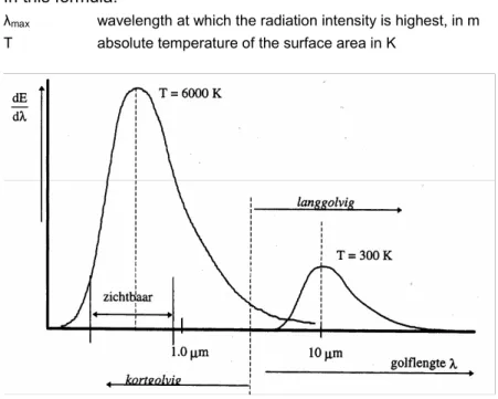
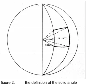
(2) Kennisbank Bouwfysica E. LI-3 ; Light – basic concepts (elaboration). Lighting variables. 1. The variables in which light is measured originally have been determined on the basis of a visual comparison of brightness: light was shed on a reference surface. The light intensity of a known light source was varied (by changing the distance or by filtering) until the brightness impression that arose was equal to the one for the light source to be measured. Amongst other sources, for this procedure a candle with a specific size and composition was used as a standard light source. At a distance of 1 metre the standard candle, seen as a focal point light source with an intensity of 1 candela, illuminated a surface with a lighting intensity of 1 lux. Later lighting measures have been derived from the energy flux that represents the light (the electromagnetic radiation). This implies that the light flux, as expressed in lumen, now is the basis; light intensity (cd) and lighting intensity (lux) are derivatives. 1.1. Light flux. Light flux is interpreted as that part of the total of electromagnetic radiation that is perceived as light by the human eye. It is expressed in the following formula:. φ = 683 .. 0.78 µm ∫ V (λ) . [dP / dλ] . dλ [lumen] 0.38 µm. In this formula: φ v(λ). light flux in lumen spectral sensitivity of the human eye. dP. radiation in watt per wavelength area dλ. For λ = 0.555 mm V(λ) = 1. By definition 1 watt of capacity emitted produces 683 lumen (the photometric radiation equivalent). 1.2. Light intensity. The relationship of light intensity and light flux is defined as follows: “The light intensity (in candela) is the light flux (in lumen) that is emitted into a specified direction per unit of solid angle (steradian).” A solid angle is defined as the part (A) taken from a sphere divided by the square distance (R2) (see figure 2).. 2 of 12 August, 2005.
(3) Kennisbank Bouwfysica E. LI-3 ; Light – basic concepts (elaboration). figure 2.. the definition of the solid angle. ω = A / R2 [sr] In this formula: ω A R. solid angle in steradians (sr) 2 surface area that is cut out, in m distance in m. The solid angle does not depend on the shape of the excision from the sphere”s surface. Since the surface of a sphere equals 4πR2, a solid angle covering the full space equals 4π steradians. The above also shows that the definition describing the relationship of light intensity and light flux is essentially based on the assumption of a light source in the shape of a focal point. However, in practice all light sources have finite dimensions. This is not problematic as long as the radius of the “imaginary” sphere surrounding the light source is many times larger than the dimensions of the light source. Obviously, the relationship of light intensity and light flux can also be described in a different way: “The lumen is the light flux that is emitted from a light source with an intensity of one candela in a solid angle of one steradian.” The entire light flux emitted by a light source is determined as follows: Ø = ∫ Iωdω [lumen] In this formula Ø Iω. light flux in lumen light intensity in cd into a specified direction. ω. solid angle in sr in which the light is emitted. If for a light source the light intensity into all directions is known, the integration must be executed for 4π steradians in order to determine the total amount of light flux emitted. If the light intensity into all directions is equally large, for the light flux it follows that Φ = 4π.I (lumen).. 3 of 12 August, 2005.
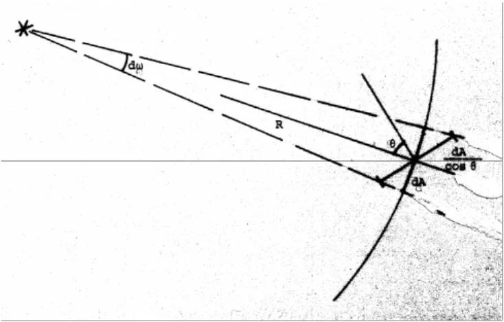
(4) Kennisbank Bouwfysica E. LI-3 ; Light – basic concepts (elaboration). 1.3. Lighting intensity E. The lighting intensity E is the light flux received per unit of surface area A. Accordingly, the measure is lumen/m2, but it has its own name: “lux”. In general, the lighting intensity will decrease with the distance squared (see figure 3).. figure 3.. the lighting intensity decreases with the square distance to the (focal point) light source (“verhouding verlichtingssterkte” = relationship lighting intensity; “lichtbron” = light source; “oppervlakteverhouding” = proportion). At a distance of 1 m the surface area taken from an imaginary sphere by a solid angle of 1 sr equals 1 m2. For a light intensity of 1 cd (= 1 lm/sr) the lighting intensity on this spot will equal 1 m/m2, i.e. 1 lux. At a distance of 2 m the same solid angle will excise a surface area four times as large. In this situation the lighting intensity will only be 0.25 lux, since the same light flux travels through a surface area four times as large. At a distance R from a light source the lighting intensity is: E = I / R2 [lux] In this formula: 2. E I. lighting intensity in lux (lumen/m ) light intensity into the direction concerned. R. distance from the (focal point) light source in m. If a surface area is not perpendicular to the light flux, the below formula holds true (see figure 4). At a distance R from the light source the lighting intensity on the surface area A is E = I/R2 lux. Since, however, the light flux does not fall on the small surface element dA, but on the larger element dA/cos, the lighting intensity decreases proportionally.. 4 of 12 August, 2005.
(5) Kennisbank Bouwfysica E. LI-3 ; Light – basic concepts (elaboration). figure 4.. if the light flux falls on the surface area at an angle, the lighting intensity decreases. E = I . cos α / R2 [lux] It will be obvious that a surface area of some minimal size which is lit by a focal point light source, will have a different lighting intensity from one point on its area to another, since the distance from the light source as well as the angle at which this source is seen, continually change. By the way, the lighting intensity does not explain the brightness with which a certain surface is perceived. For this the extent to which and the way in which the surface reflects light are criteria. 1.4. Luminance and brightness. The brightness with which a certain surface area is perceived is a subjective notion, determined by the observer”s physiological and psychological circumstances. In order to be able to describe brightness proportions, the physical measure “luminance” (L) has been introduced (also see figure 5).. figure 5.. measures for determining the luminance ( netvlies = retina ; beeld = image ; ooglens = lens ; “verlicht oppervlak” = surface lit ; “schijnbare oppervlakte van dA” = apparent surface of dA). 5 of 12 August, 2005.
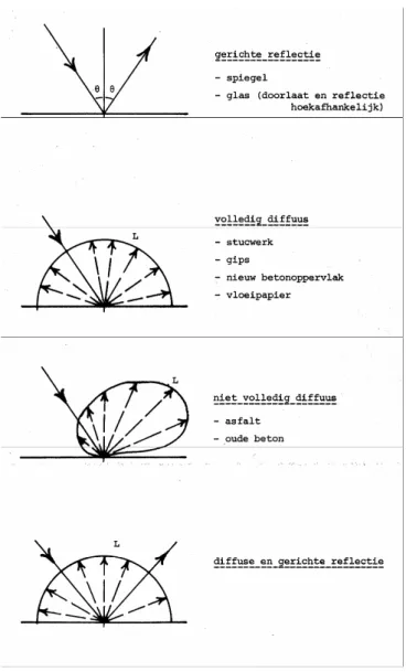
(6) Kennisbank Bouwfysica E. LI-3 ; Light – basic concepts (elaboration). The luminance may be regarded as the light intensity into a specified direction per unit of surface area from a light source or a surface that is lit. This is represented in the following formula: L(θ) = dI(θ) / dA . cos θ [cd/m2] In this formula dI(θ) is the light intensity as emitted by a surface element dA into the direction θ. On the eye”s retina an image is formed, the surface of which is not only proportional to the distance to the surface lit, but also – and especially – to the “apparent” surface area of the element dA (dAapparent = dA.cos θ). The light flux producing the image on the retina is proportional to the lighting intensity emitted and the distance from the eye to the surface element dA. The amount of lumen received per m2 of retina depends on the size of the surface element dA and on the distance from here to the eye. After all, if the size of the surface element is halved, the light intensity emitted, and consequently the light flux emitted in lumen per steradian, will be twice as small, as will be the image on the retina; and so the amount of lumen received per m2 of retina will remain equal. If the distance between the eye and the surface element is doubled, the lighting intensity near the eye will be four times as small, as a result of the light emitted by the surface element. Since the image on the retina will also be four times as small, the light flux received (in lumen) per m2 of retina will remain equal as well. For a surface area with diffuse emission or reflection the luminance into all directions is equal. It is true that the light intensity at larger angles decreases, but the apparent surface decreases proportionally, so that the luminance remains equal. Practically speaking, the same applies to the subjective notion of brightness. The notions of brightness and luminance are often confused. However, when speaking of measurable variables, one should always use luminance. 2. Surfaces 2.1. Diffusely reflecting or emitting surfaces. A surface emit “diffuse” light when the luminance in each spot of the surface is equal into all directions. A surface area may emit light through heating (glowing steel plate), through passing light (opal cover of a lighting ornament) or through reflection of light fallen on it. In the case of reflection the surface area must emit diffuse light, irrespective of the direction of incidence of the light. Approximately, stucco, plaster, new concrete and the like comply with this requirement, contrary to a mirror, in which incident light is reflected at the same angle. Hybrids are also possible (see figure 6).. 6 of 12 August, 2005.
(7) Kennisbank Bouwfysica E. LI-3 ; Light – basic concepts (elaboration). figure 6.. various ways of reflecting. “gerichte reflectie” = directed reflection. “volledig diffuus” = completely diffuse. - mirror - glass (passing and reflection angle-dependent. - stucco - plaster - new concrete - blotting paper. “niet volledig diffuus” = incompletely diffuse - asphalt. “diffuse en gerichte reflectie”= diffuse and directed reflection. - old concrete. The light intensity emitted from a diffuse surface has its maximum in the direction that is perpendicular to the surface. When the light is considered from a specific direction, the apparent surface comes into play again. I(θ) = L . Aapparent = L . A . cos θ = I0 . cos θ [cd]. 7 of 12 August, 2005.
(8) Kennisbank Bouwfysica E. LI-3 ; Light – basic concepts (elaboration). In this formula: I I0. light intensity into the direction θ in cd light intensity in cd perpendicular to the surface area. L A. luminance of the surface into all directions 2 surface in m. θ. angle as compared to the perpendicular on the surface. For the total light flux radiated from a flat surface (for a hemisphere) the following formula is to be found: Ø = ∫ ∫ L . cos θ . dω . dA = ∫ L . A . cos θ . d = π . L . A [lumen] h.s. A h.s. In this formula: h.s.. means hemisphere. dω. represents a solid angle element within that hemisphere other variables as in previous formula. 2.2. Reflection coefficient. The reflection coefficient of a surface is defined as: r = dØreflected / dØincident When the reflection coefficient (r) of a specific diffusely reflecting surface is known, for the luminance it follows that: L = Ø / (π . A) = r . E / π [cd / m2] In this formula: Ø. incident light flux in lumen. A r. surface in m reflection coefficient. E. lighting intensity in lux (lumen/m ). 2. 2. This latter formula clearly illustrates that luminance and lighting intensity are completely different measures. As explained before, the lighting intensity is determined by the incident light; the surface on which this light falls has no influence on this whatsoever. The luminance of a surface – what we perceive – on the one hand, of course, also depends on the lighting intensity of the surface; however, on the other hand particularly on the characteristics of the surface, such as the reflection factor. Different surfaces have different luminances at the same lighting intensity. This reflection factor is given in table 1 for some materials. Incidentally, it is clear that the reflection factor need not be identical for all wavelengths. If it is, though, with incident white light the surface will become more and more grey for lower and lower reflection factors, until it will be black for r = 0. If the surface only reflects light of a specific wavelength, with incident white light the surface will show the “colour” belonging to that wavelength. For red light falling on a green surface, this surface will look black (r = 0) for the wavelength belonging to red light.. 8 of 12 August, 2005.
(9) Kennisbank Bouwfysica E. LI-3 ; Light – basic concepts (elaboration). reflection factors various materials. reflection factors colours. material. colour. reflection. reflection factors. factor white plaster (new). 0.70 - 0.80. light. middle. dark. white plaster (old). 0.30 - 0.60. concrete (new). 0.40 - 0.50. white. 0.80. 0.70. -. concrete (old). 0.05 - 0.15. grey. 0.60. 0.35. 0.20. brick (new). 0.10 - 0.30. black. -. -. <0.04. brick (old). 0.05 - 0.15. yellow. 0.70. 0.50. 0.30. aluminium (shiny). 0.80 - 0.85. beige. 0.65. 0.45. 0.25. aluminium (dull). 0.50 - 0.60. brown. 0.40. 0.20. 0.07. dark woods. 0.10 - 0.30. red. 0.35. 0.20. 0.10. light woods. 0.30 - 0.50. green. 0.50. 0.25. 0.12. writing paper. 0.70 - 0.80. blue. 0.55. 0.25. 0.08. table 1. 3. reflection factor of various materials and for various colours. General lighting formula For the calculation of the lighting intensity for light sources having such dimensions that they can no longer be considered as focal point sources, they can be projected into a point P on a standard sphere (radius R = 1 m) wrapped around this point (see figure 7). Whether or not a light source may still be seen as a focal point source depends on the accuracy aimed for. And this depends on the proportion of the largest size of the light source (a) to the distance between the surface lit and the light source (R). The error made is: for a = 0.1 . R approx 0.5% a = 0.2 . R approx 1% a = 0.5 . R approx 5%. 9 of 12 August, 2005.
(10) Kennisbank Bouwfysica E. LI-3 ; Light – basic concepts (elaboration). figure 7.. projection of light sources on the “standard sphere” and on its base (“oppervlakte-elementje” = surface element ; diffuus stralend vlak” = diffusely radiating surface ; “schijnbaar oppervlak” = apparent surface ; oppervlak = surface ; ruimtehoek = solid angle; “projectie van het op de eenheidsbol geprojecteerde vlak” = projection of the surface projected on the standard sphere). As long as diffusely emitting light sources or diffusely reflecting surface areas are concerned, the angle at which the surface is seen is not of importance, since for diffusely emitting surfaces the luminance is equally large into all directions. Suppose the surface area has been divided into surface elements in such a way that these cover a solid angle dω, the apparent surface of such an element will be R2.dω (also see the definition of a solid angle). In this situation, the light intensity emitted into the direction of P will be: dI = L . R2 . dω [cd] Where: dI 2 R .dω. light intensity emitted into the direction of P apparent surface of an element of the diffusely emitting surface. The surface element in point P can be considered as a focal point light source emitting a light source dI into the direction of P. Its contribution to the lighting intensity in point P is: dI . cos θ dE = ----------- [lux] R2 or: L . R . dω . cos θ dE = ----------------------- = L . dω . cos θ [lux] R2 It is also possible to project the surface element on the standard sphere around P. Since the solid angle remains the same, for this projected surface the same luminance can be kept for an apparent surface d (the distance being R = 1 m), so that dI = L . dω [cd] For a distance R = 1 m the contribution to the lighting intensity in P will now be : dE = dI . cos θ [lux] or: dE = dI . dω . cos θ [lux] This produces exactly the same result as above. The total lighting intensity in P is found by adding up the contributions of all surface elements:. E=. L∫ L ⋅ cos θ ⋅ dω [lux ]. h.b .. In figure 7 it is also to be seen that cos dω is the projection on the flat surface of the small surface area taken out of the standard sphere by the solid angle dω. Cos θ.dω may be called the projected solid angle (dω proj), so that:. 10 of 12 August, 2005.
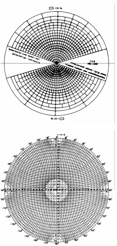
(11) Kennisbank Bouwfysica E. LI-3 ; Light – basic concepts (elaboration). E=. L³ L ⋅ dω [lux ] proj. h .b.. and for an evenly distributed luminance:. E = L ⋅ L³ d ω proj [lux ] h.b .. Thus, the lighting intensity in a specific point – caused by a diffusely emitting surface – is to be found, first, by projecting the surface on a standard sphere wrapped around this point, and, subsequently, by projecting this projection (viz. the one on the surface of the sphere) on the base of the standard hemisphere. The surface of this projection multiplied by the original luminance is the lighting intensity. In this way, the lighting intensity out of doors under a uniform sky with luminance L is to be found as:. E = L ⋅ L∫ d ω proj = π ⋅ L [lux ] h.b.. This is true since the projections of all surface elements cover the entire base of the standard hemisphere and the size of this is π m2. For cases in which the light sources have random, finite dimensions the solution is less simple. However, for these situations there are good and user-friendly computer programs, that are frequently used in practice. It is also possible to use a graphical method in order to be able to quickly say something about a particular situation. An example is the method mentioned in the lecture notes “General Lighting Science” by the Technical University Eindhoven. Here the surface of the standard sphere is divided into 1000 surface areas, each of these contributing equally to the lighting intensity, starting from a completely even distribution of the luminance. Of course, these surface areas will be larger and larger as they are situated lower on the sphere. For equal sizes of the surface areas the light intensity emitted into the direction of P will be equally large. However, since the angle at which the light is shed will deviate more and more from the perpendicular on the base, the contribution to the lighting intensity would decrease as they lay lower on the sphere. The projections of these surface areas produce the diagram in figure 8. With the aid of a second diagram, a “radian diagram” (figure 9), the projections of the light sources to be considered can be plotted in on the sphere”s base. How exactly this is to be done, will be discussed in Daylight Lighting. As always, diagram are an excellent method for determining the daylight factor in a specific situation. For daylight lighting also other luminance distributions are used than even ones. The diagram in figure 8 also represents the situation for a distribution (C.I.E.) at which the luminance perpendicularly above the surface considered is three times as high as the one parallel to the surface (the horizon). In that situation the contribution of the lower parts of the “standard sphere” clearly decreases, whereas the higher parts contribute more; also see the diagram.. 11 of 12 August, 2005.
(12) Kennisbank Bouwfysica E. LI-3 ; Light – basic concepts (elaboration). figure 8:. diagram for determining the contribution that surface elements of the “standard sphere” have to the lighting intensity (“hemelfactor voor hemel met gelijkmatige luminantie” = sky factor for sky with even luminance; “hemelkomponent voor volledig bedekte hemel – zonder glasverliezen” = sky component for completely overcast sky (C.I.E.) without glass losses. 12 of 12 August, 2005.
(13)
Afbeelding

+3
GERELATEERDE DOCUMENTEN
The major research aim of this thesis is contributing to a better understanding of the role of the light industry in the governance of discontinuation of the ILB
Er kan wel aangenomen worden dat het product een bijdrage zal leveren aan de motoriek van het kind. In veel babyproducten zit om deze reden een spiegel. De spiegel van de Look
• If the caption is typeset as ”short” (centered), the content of the caption is evaluated only once, just like the original definition included in article, report, and book. •
RQ2: To what extend does lamp location influence the relative importance of the variables described in the Theory of Planned Behavior.. This research attempts to discover
Naarmate de temperatuur toeneemt, neemt de soortelijke
2) Zet er nog een led in een andere kleur bij die je ook kan bedienen met
For photon energies far below the electron mass, the photon-photon scattering process can be described by the Euler-Heisenberg Lagrangian, which is a low energy effective field
Originality/value – The paper benefits from a unique mix of: epistemic note on tourism, leisure, and the future; original urban futures scenarios and design concepts from a world
