DECARBONISATION OPTIONS
FOR THE DORDRECHT
CHEMICAL CLUSTER
Marian Alejandra Rodriguez, Ton van Dril,
Silvana Gamboa Palacios
04 January 2021
Decarbonisation options for the Dordrecht chemical cluster
© PBL Netherlands Environmental Assessment Agency; © TNO The Hague, 2021
PBL publication number: 4558
TNO project no. 060.33956 / TNO 2020 P11629
Authors
M.A. Rodriguez, A.W.N. van Dril and S. Gamboa Palacios
Acknowledgements
The authors kindly acknowledge input and review byMarc Reijmers (Chemours Dordrecht), Ton Knijnenburg (DuPont Dordrecht) and Willem Buitelaar (DuPont Dordrecht).
MIDDEN project coordination and responsibility
The MIDDEN project (Manufacturing Industry Decarbonisation Data Exchange Network) was initiated and is also coordinated and funded by PBL and ECN part of TNO (which is named TNO EnergieTransitie after 1-1-2020). The project aims to support industry, policymakers, analysts, and the energy sector in their common efforts to achieve deep decarbonisation.
Correspondence regarding the project may be addressed to:
D. van Dam (PBL), Dick.vanDam@pbl.nl, or S. Gamboa Palacios (TNO), Silvana.Gamboa@tno.nl
This publication is a joint publication by PBL and TNO EnergieTransitie and can be
downloaded from: www.pbl.nl/en. Parts of this publication may be reproduced, providing the source is stated, in the form: Rodriguez, M.A., Van Dril, A.W.N., and Gamboa Palacios, S. (2021), Decarbonisation options for the Dordrecht chemical cluster. PBL Netherlands Environmental Assessment Agency and TNO EnergieTransitie, The Hague.
PBL Netherlands Environmental Assessment Agency is the national institute for strategic policy analysis in the fields of the environment, nature and spatial planning. We contribute to improving the quality of political and administrative decision-making by conducting outlook studies, analyses and evaluations in which an integrated approach is considered paramount. Policy relevance is the prime concern in all of our studies. We conduct solicited and
unsolicited research that is both independent and scientifically sound.
TNO EnergieTransitie has a twofold mission: to accelerate the energy transition and to strengthen the competitive position of The Netherlands. TNO conducts independent and internationally leading research and we stand for an agenda-setting, initiating and supporting role for government, industry and NGOs.
This report was reviewed by Chemours Dordrecht and DuPont Dordrecht. PBL and TNO remain responsible for the content. The decarbonisation options and parameters are explicitly not verified by the companies.
Contents
Summary 4
INTRODUCTION
6
1
DORDRECHT CHEMICAL CLUSTER
8
1.1 Location, description, and history 8
1.2 Local context and relevant projects 9
1.3 The Chemours Company 10
1.4 DuPont Dordrecht 11
1.5 The Dow Chemical Company 13
2
PRODUCTION PROCESSES
14
2.1 Chemours 14
2.2 DuPont 22
2.3 Dow 29
3
DORDRECHT CHEMICAL CLUSTER PRODUCTS AND
APPLICATIONS
31
3.1 Chemours: Fluoroproducts Market Overview 31
3.2 DuPont: POM overview 34
4
OPTIONS FOR DECARBONISATION
40
4.1 Decarbonisation of heat supply 41
4.2 Energy Efficiency 47
4.3 CCS/CCU 47
4.4 Bio-based feedstocks 50
4.5 Chemours specific options 50
4.6 DuPont specific options 53
4.7 Dow specific options 56
4.8 Summary of decarbonisation alternatives per company 58
5
DISCUSSION
66
REFERENCES
69
FINDINGS
Summary
This report presents the current situation of the Dordrecht chemical cluster, which is composed by production locations of three different companies: Chemours, DuPont, and Dow. Chemours is dedicated to the production of fluoropolymers and fluoroelastomers, DuPont produces polyoxymethylene, and Dow produces copolymers of ethylene.
Table 1 shows the main feedstock, products, main technologies, and an estimation of energy consumption, and greenhouse gas emissions1 of the three companies.
Table 1 Overview of the three companies (Elektronisch Milieujaarverslag, 2018)
Company Chemours DuPont Dow Total Dordrecht
Site
Main Feedstock • Chloroform
• Hydrofluoric acid • Methanol • Polyethylene • Acrylic acid • Maleic anhydride Product • Polytetrafluoroethylene (PTFE) Teflon™ • Fluorinated ethylene-propylene (FEP) Teflon™ • Chlorotrifluoroethylen evinylidene fluoride (FPM/FKM) Viton™ • Polyoxymethylene
(POM) Delrin® • Ionomer of ethylene acid copolymer Surlyn™ • Resin Adhesives Bynel™ • Modified polymers Fusabond™ Technology • Fluorination of Chloroform to produce Chlorodifluoromethan e (HCFC-22) • Pyrolysis of HCFC-22 to produce Tetrafluoroethylene (TFE) and pyrolysis of TFE to produce Hexafluoropropylene • Homopolymerization and copolymerization of TFE and HFP • Catalytic oxidation of methanol to produce formaldehyde (Formox process) • Polymerization of formaldehyde to produce polyoxymethylene (POM) • Compounding (melting the polymer and mixing with additives to produce granules) • Reactive extrusion of polyethylene • Granulation Estimated production capacity 2018 (kilotonnes, kt) 15-25 90-100 40-45 Estimated energy consumption (TJ) 805 1,284 192 2,282 CO2 emissions (kt/year) 15 42 0 57 CO2 emissions Percentage2 24% 76% 0 100% F-gases emissions (kt CO2 eq/year) 491 0 0 491 F-gases emissions percentage 100% 0 0 100%
Currently, the main source of steam of the site is a waste to energy plant, owned by HVC, which is located adjacent to the cluster. HVC provides around 840 TJ of steam per year, converted in a heat exchanger operated by Chemours to supply the different processes in the industrial facility. The steam supply is also connected to the urban heat network of
Dordrecht. Natural gas is mainly used to feed furnaces and the two back-up boilers owned by Chemours and DuPont. There is no electricity production on-site, so currently all the
electricity supply comes from the grid.
The vast majority of the emissions of greenhouse gases occurs at Chemours, in the form of fluorinated gases (F-gases), which are man-made gases with a large global warming potential. The main methods to reduce F-gases emissions, besides the ongoing strategies, are increasing the efficiency of the current thermal converter and implementing plasma technology to destroy F-gases.
Regarding CO2 emission reduction,the main opportunities are related to fuel substitution. Around 65% of the CO2 emissions of the site are from natural gas combustion for boilers and furnaces. Although the steam production related emissions have been reduced in the past years through external supply and heat integration, there are still opportunities by using carbon-free electricity, blue or green hydrogen, and sustainable biomass. Carbon capture and storage is included as an alternative to reduce emissions not only from natural gas combustion, but also from residual gases combustion, which represents around 30% of the total CO2 emissions. Further alternatives include biobased feedstocks and recycling.
FULL RESULTS
Introduction
This report describes the current situation for Dordrecht Chemical Park in The Netherlands and the options and preconditions for its decarbonisation. Besides, it includes alternatives for reducing fluorinated gases (F-gases) emissions for one of the companies located in this industrial site due to the high global warming potential of these gases. The study is part of the MIDDEN project (Manufacturing Industry Decarbonisation Data Exchange Network). The MIDDEN project aims to support industry, policymakers, analysts, and the energy sector in their joint efforts to achieve deep decarbonisation. The MIDDEN project will update and elaborate further on options in the future, in close connection with the industry.
Scope
The companies located in Dordrecht at the Baanhoekweg industrial chemical park are: • The Chemours Company
• DuPont Dordrecht
• The Dow Chemical Company.
Production processes include:
Chemours
• Fluorination of chloroform to produce chlorodifluoromethane (HCFC-22) • Several separation steps, including distillation and drying
• Neutralization • Gas compression
• Pyrolysis of HCFC-22 to produce tetrafluoroethylene (TFE) and pyrolysis of TFE to produce hexafluoropropylene
• Homopolymerization and copolymerization of TFE and HFP • Thermal conversion of gases
• Blending of gases.
DuPont
• Catalytic oxidation of methanol to produce formaldehyde (Formox process) • Polymerization of formaldehyde to produce polyoxymethylene (POM)
• Compounding (melting the polymer and mixing with additives to produce granules) • Biogas production (Anaerobic water treatment)
• Incineration of by-products and residual process gases.
Dow
• Reactive extrusion of polyethylene • Granulation
Products include:
Chemours
• Polytetrafluoroethylene (PTFE) Teflon™ • Fluorinated ethylene-propylene (FEP) Teflon™
• Chlorotrifluoroethylenevinylidene fluoride (FPM/FKM) Viton™
DuPont
• Polyoxymethylene (POM) Delrin®
Dow
• Ionomer of ethylene acid copolymer Surlyn™ • Resin Adhesives Bynel™
• Modified polymers Fusabond™
The main options for reducing greenhouse gases emissions and energy consumption are:
Chemours
• F-gases: Plasma technology for F-gases destruction.
• CO2: energy efficiency, electrification, hydrogen, heat pumps, biomass, recycling, and CCS.
Dupont
• CO2: electrification, hydrogen, heat pumps, biomass, recycling, CCS/CCU, biobased feedstocks.
Dow
• CO2: hydrogen, recycling, biobased feedstocks.
The report is elaborated using information and data from 2018 and is presented in separated sections per company for each chapter.
Reading guide
Section 1 introduces the chemical cluster located in Dordrecht, its history, and gives an overview of the site's companies. Section 2 describes the current situation of the production processes of each company, and Section 3 describes the relevant products of these
processes and the main market insights; options for decarbonisation are presented and evaluated in Section 4. The timeframe of implementation and main challenges are briefly discussed in Section 5.
1 Dordrecht chemical
cluster
1.1 Location, description, and history
This chemical cluster or park is located in Baanhoekweg 22, in Dordrecht, part of the province of South Holland. The location is close to the Merwede river and the populated residential areas De Staart and Sliedrecht-Oost. The residents of Dordrecht, Papendrecht, and Sliedrecht are actively involved in The Neighbours Council of the companies located in this site. This council is an initiative to have a frequent and open dialogue with the
community about current affairs, licenses, environment, and funding initiatives. The council involves the management boards of the companies as well (Burenraad DuPont and
Chemours, 2020)
Dordrecht chemical cluster was originally a factory complex of DuPont de Nemours, with an area of 55 hectares. DuPont de Nemours was established in The Netherlands in 1959 and started operations in Dordrecht in 1962 with the fiber factories of Orlon™ and Lycra™ (DuPont, 2020a). Around 1967 the Teflon factory™ was put in operation, and then, in the 1970’s, the Delrin® factory was constructed (Dordrecht regional archives, 2020). Years later, other processes of DuPont were added to the industrial complex. However, several business transactions took place over time, including the sale of the DuPont textile segment, including Lycra (INVISTA) to Koch Industries in 2004 (Wilson, 2012). Another change was the closure and the demolition of the Lycra factory located in this industrial site in 2009 (DuPont, 2017). Subsequently, in 2015, the Chemours company was formed and separated as a spin-off of DuPont for the performance chemicals business, including the fluoroproducts segment. Afterwards, in 2017, a merge between DuPont and Dow Chemical was announced, with a further split into three new companies: Corteva, the new DuPont, and the new Dow. As a result of this split, DuPont's ethylene copolymers production facility in Dordrecht was allocated to the new Dow. These business transactions led to the reorganisation of the industrial site, currently owned by Chemours, with three different companies: The Chemours Company, DuPont, and The Dow Chemical Company. Although these companies are
independent, they still have a shared environmental permit associated with the entire site. Nevertheless, according to Chemours, DuPont, and Dow information, each company recently applied for a separate permit under evaluation of the South Holland province environmental service (DCMR Milieudienst Rijnmond). Chemours and DuPont participated jointly in the voluntary long-term agreement on Energy Efficiency (MEE covenant), so both companies have an Energy Efficiency Plan (EEP). Once the companies have separate permits, each company will participate separately.
1.2 Local context and relevant projects
Different industrial processes take place in the industrial cluster, which implies high energy consumption. Historically a cogeneration plant operated in this site and was the primary source of carbon dioxide (CO2) emissions. This plant combusted natural gas to produce the steam and electricity required by the different processes. Nevertheless, the plant was shut down in 2018, and its steam production was replaced by an external supply, thanks to the cooperation project between HVC, DuPont, and Chemours. HVC operates a waste-to-energy plant located adjacent to the industrial cluster, which has supplied steam to the site since 2014. Municipal solid waste is incinerated to produce heat, which required a 1 km steam pipe connecting HVC to the industrial cluster. The amount of steam supplied has increased
considerably, reaching to 400 kt/year in 2017. Due to that shift from burning natural gas to HVC steam supply, the site has reduced its CO2direct emissions by over 60%.
According to the HVC business manager, one of the main barriers starting the project was the quality of the steam produced by HVC; the steam did not meet the requirements of the processes, so it was necessary to invest in a heat exchanger to convert the steam from 40 bars to 22 bars. The steam from HVC is 55% renewable (Chemours, 2018), a percentage based on the incinerated waste composition. This cooperation agreement with HVC is aligned with Dordrecht municipality’s goals of becoming energy-neutral by 2050, with a heat network that also supplies the urban area(Dordt Duurzaam, 2016). Because of the steam system's existing connections on the site, Chemours transfers part of the steam to Dow and Du Pont. Therefore, these companies also benefit from this measure to reduce their CO2 emissions. Although in 2018 there was a single environmental permit for the complete site, a new independent application has been sent by each company to the South Province
environmental agency, and is currently under evaluation. Below, there is an aerial picture of the Dordrecht site, indicating the operations of the three companies (Chemours, Dow Chemical, and DuPont) and the HVC plant's location.
In the next sections, each company is separately described.
1.3 The Chemours Company
The Chemours Company is a multinational American chemical company created as a spin-off from DuPont in 2015. Chemours produces chemical products in three main categories: Titanium Technologies, Fluoroproducts, and Chemical solutions. Chemours Netherlands B.V. Dordrecht site is a complete subsidiary of The Chemours Company. Its focus is on
fluoroproducts: manufacturing industrial fluoropolymer resins and blending refrigerants3. With more than 500 employees and operating 24-7, Chemours Dordrecht site is the principal private employer in Dordrecht (Burenraad DuPont and Chemours, 2018). Chemours annual production capacity of fluoropolymers is around 15-20 kt, including PTFE, and FEP polymers, under the brand Teflon™ and FKC elastomers, under the brand Viton™ (Elektronisch
Milieujaarverslag (EMJV), 2018; own calculations). The main raw materials used for the production of fluoropolymers are chloroform (Trichloromethane) and HF (Hydrofluoric Acid). These materials are used to produce HCFC-22, which is only intended as a feedstock in the subsequent production of monomers4; these monomers are then used to produce the final polymers and elastomers.
Different by-products of the fluorination of chloroform are produced, including HFC-23. Due to this gas's high global warming potential5, this is the main source of GHG emissions. Chemours annual emissions of HFC-23 are around 15 tonne/year (EMJV, 2018), which equals 186 kt CO2-eq/year. Besides these emissions, there are other diffuse F-gases emissions in two additional steps of the process6. First, during the blending of refrigerants, some HFCs are emitted, and second, during the production of the monomers mentioned above TFE and HFP. During the pyrolysis to produce the monomers, low amounts of hydrofluorocarbons (HFCs), perfluorocarbons (PFCs), and chlorofluorocarbons (CFCs) are produced; however, due to the high GWP of these gases, the CO2 equivalents are high (see table 1). Moreover, although their monomers are water-based, they use a solvent during the pelletization of polymers. This solvent can generate some diffuse emissions as well.
Through different projects, Chemours has reduced its GHG emissions to air. These projects include process efficiency to reduce HFC-23 production, the circulation loop system in the monomer plant, and a final thermal treatment of the waste gases from the different processes, for which a thermal converter was installed in 2002. Despite these reduction strategies, there are still significant emissions, mainly when the thermal converter is interrupted. To reduce these diffuse emissions, Chemours is now working on stop protocols and also on increasing the buffer capacity of emissions (increase emissions storage capacity to incinerate later). Although the different processes also use, and in consequence emit, other critical substances such as Gen-X, we do not focus our research on those substances; this study's scope is only on GHG emissions.
As mentioned in section 1.2, the main Chemours CO2 emissions source was the cogeneration plant. However, the cogeneration plant is no longer in operation. One unit was already withdrawn from the site, and the other one was turned off. Now Chemours receives steam from HVC and DuPont (waste steam) and recently installed two backup boilers, to be used as a backup for the HVC steam supply. The steam supply from HVC and DuPont has led to a significant reduction of CO2 emissions. The CO2 emissions related to energy consumption represent less than 4% of the Chemours total GHG emissions per year. In the table below, there is a summary of the main GHG emissions of Chemours, including not only CO2 but also F-gases:
3 Chemours Dordrecht does not produce refrigerants; the blends are made using imported refrigerants. 4 In the past Chemours produced HFC-22 also as final product (mainly as a refrigerant), but due to
Montreal Protocol this was phased-out. Now its production is only permitted as a feedstock. HFC-23 global warming potential is 12.400 times than CO2
Table 2 Chemours GHG Emissions and Main Sources of Emissions (Elektronisch Milieujaarverslag, 2018 and own estimations)
Substance Amount (tonne) GWP CO2 eq (kt)
CO2 15,000 - 15 CFCs 20 8,463 169 HFC-23 15 12,400 186 Other HFCs 24 1,716 41 Total PFCs 11 8,629 95 Total F-gases 70 491 Total of GHG emissions 506
Because the total CO2 emissions are taken from the NEA report, these do not include the electricity-related (scope 2) emissions. In the case of Chemours, the emissions related to the electricity from the grid are around 29 kt7. The analysis of the emissions was carried out using information and numbers from 2018, which, according to Chemours, was a turnaround (TAR) year. Hence, the fugitive emissions of F-gases from the refrigeration machines are expected to be somewhat lower in normal operating conditions.
Regarding energy consumption, all the industrial methods of production of the main fluoropolymers require chlorination/fluorination of hydrocarbons and a further
dehydrohalogenation using high temperatures. Due to these processes, the production of fluoropolymers is energy-intensive. As an average, to produce 1 tonne of TFE, the overall energy requirement is more than 10.000 kWh/tonne (Hintzer and Schwertfeger, 2014). In the case of Chemours, 30% of the energy consumption is electricity, 29% natural gas, and 41% steam.
The table below illustrates the energy overview of Chemours in 2018:
Table 3 Chemours Net Energy Consumption (EMJV, 2018; information shared by Chemours)
Energy Carrier Amount Unit of Measure TJ Percentage (%)
Electricity8 68,055 MWh 245 30
Natural Gas 7,341,818 Nm3 232 29
Steam 117,700 tonne 328 41
Total 805 100
1.4 DuPont Dordrecht
DuPont Dordrecht is part of DuPont de Nemours Inc., an American corporation created after the merge between DuPont and The Dow Chemical Company (DowDuPont) and the
subsequent division into three separate companies, one of them DuPont. The predecessor DuPont was established in 1802 in Wilmington, Delaware. The new portfolio of DuPont is based on specialty products, including segments such as safety and construction, transportation, electronics, industrial biosciences, and advanced polymers. Besides the Dordrecht plant, DuPont has four locations in The Netherlands: Landgraaf, Leiden, Ouderkerk aan den IJssel and Zaandam (DuPont, 2020b).
7 According to KEV 2020, the grid electricity emissions in 2018 (integral method) were 0.43 kg CO2/kWh. 8 Electricity was converted to TJ using the final energy equivalent 0.0036 TJ/MWh.
The Dordrecht DuPont plant has 250 direct employees, and its production, which operates 24-7, is focused on the advanced polymers segment. According to DuPont, this plant, with an estimated annual production capacity of around 90-100 kt, produces the homopolymer POM (Polyoxymethylene) under the brand Delrin®. The main raw material is methanol, used for the production of formaldehyde; the formed formaldehyde polymerizes to POM in a
subsequent step. Later, a compounding process takes place to melt the polymer and mix it with some additives to produce granules.
In terms of CO2 emissions, according to a recent Life Cycle Assessment (cradle to gate) of the DuPont factory, two-thirds of the carbon load comes from steam, electricity, and methanol used as a raw material. The rest comes mainly from other raw materials. The company has been working on energy efficiency, heat recovery, and steam production as part of its energy efficiency plan 2017-2020 (DuPont, 2020). The main source of CO2
emissions is the furnace to burn liquid and residual process gases; this furnace operates with natural gas and biogas produced in the anaerobic water treatment plant. The DuPont CO2 emissions per year are around 35 kt, 35% from burning natural gas, and the rest mainly from burning by-products and residual process gases (DuPont corporate responsibility report, 2019; EMJV, 2018). Table 4 illustrates the main CO2 emissions, scope 1, from DuPont, and table 5, its energy overview.
Table 4 DuPont CO2 Emissions and Main Sources of Emissions
(EMJV, 2018; information shared by DuPont)
Emission Source CO2
(kt) Process Emissions
Emission control system (ECS) unit
1.0
Natural gas combustion 24.0
Combustion of biogas9 2.5
Combustion of residual gases10 14.5
Total Emissions 42.0
Table 5 DuPont Net Energy Consumption (EMJV, 2018; information shared by DuPont)
Energy Carrier Amount Unit of Measure TJ Percentage
Electricity11 94,000 MWh 338 26%
Natural Gas 13,397,428 Nm3 424 33%
Steam 186,805 Ton 521 41%
Total 1,283 100%
DuPont emissions related to the electricity from the grid (scope 2 emissions) are around 40 kt12.
Due to the formaldehyde production reaction's exothermic nature, there is a heat-recovering process to produce steam in a boiler. This steam is used in the Delrin® chemical plant, in which the total energy consumption has decreased, because of different strategies, such as energy integration and insulation. Due to the complexity of the formaldehyde process, heat
9 Biogas is produced from a biological process but does not imply the use of biomass, thus its related emissions
are included in the analysis.
10 These emissions are from the combustion of by-products and residual gases. 11 Electricity was converted to TJ using the final energy equivalent 0.0036 TJ/MWh
recovery requires a high cooling capacity. Additionally, DuPont receives steam from HVC but also from a backup boiler in case HVC supply is interrupted. Moreover, during the
incineration of by-products and residual gases from the process, the heat released is used to produce steam; the steam produced is used in other parts of the process. Residual steam from DuPont processes is sent to Chemours.
Looking into the future, DuPont sees CO2 reduction opportunities related to bio-based raw materials, green electricity, and steam production from renewables.
1.5 The Dow Chemical Company
The Dow Chemical Company is an American multinational corporation founded in 1897; its headquarters are located in Midland, Michigan, United States. As part of its broad portfolio, Dow has products for consumer care, infrastructure, and packaging industry. In The Netherlands, Dow has been active since 1955, with production sites at Terneuzen and
Delfzijl, and also in Dordrecht since 2019 (Dow, 2020). After the merge with DuPont, and the subsequent split, the DuPont ethylene copolymer factory in Dordrecht was transferred to Dow. This factory started operations in Dordrecht in 2011 with two production lines for specialty chemical intermediates, which operates 24-7 and has around 45 employees.
The copolymer factory is focused on the production of the ionomer of ethylene acid
copolymer, under the brand Surlyn™, adhesive polymers under the brand Bynel™, and other modified polymers under the brand Fusabond™. The main raw materials are polyethylene, acrylic acid, and maleic anhydride.
Dow’s energy sources are mainly electricity and steam from Chemours. The energy is used for the reactors, blenders, and extruders. There are no direct emission sources such as furnaces or boilers.
Table 6 Dow Energy Overview (General information shared by
Dow and official information about the whole site from EMJV, 2018)
Energy Carrier Amount Measure Unit of TJ Percentage (%)
Electricity13 53,417 MWh 194 99%
Steam 72 tonne 0.2 1%
Total 194.2 100%
Dow emissions related to the electricity from the grid (scope 2 emissions) are around 23 kt14.
13 Electricity was converted to TJ using the final energy equivalent 0.0036 TJ/MWh.
2 Production processes
This chapter describes and quantifies the main processes taking place at Dordrecht chemical cluster. An overview of the main chemical reactions and the energy and materials flows is developed in separate sections on the three companies, based mainly on literature review and information shared directly by the companies.
2.1 Chemours
2.1.1 Fluoropolymers Overview
Chemours produces different fluoropolymer and elastomer grades under two main brands:
Teflon™: Polytetrafluoroethylene (PTFE) and Fluorinated ethylene-propylene (FEP) Viton™: Chlorotrifluoroethylenevinylidene fluoride (FPM/FKM)
These products are based on the monomer Tetrafluoroethylene (TFE) and other
comonomers, such as HFP (Hexafluoropropylene) and VDF (Vinylidene fluoride). TFE, the most common monomer used in the production of fluoropolymers (Drobny, 2009), is produced by the pyrolysis of HCFC-2215, which in turn, is produced by the fluorination of chloroform with hydrofluoric acid (HF).
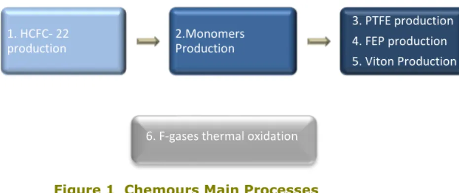
The main production processes that take place at Chemours are illustrated in the diagram below:
Figure 1 Chemours Main Processes
Besides these processes, an additional blending plant of imported refrigerants is located at the Chemours facility.
There are no descriptions of the Chemours processes publicly available. Thus, sections 2.1.2, 2.1.3, and 2.1.4 illustrate mainly findings from a thorough literature review, including publications and commercial patents, and assumptions about Chemours process
configurations. The methods of production subsequently described were selected as the most widely used at the industrial level.
1. HCFC- 22
production 2.Monomers Production
3. PTFE production 4. FEP production 5. Viton Production
2.1.2 HCFC-22 Production
The next schematic diagram illustrates an overview of the main steps involved in the production of HCFC-22. It includes the ranges of main inputs and outputs of materials and energy requirements per year. The black arrows represent the main raw materials and products; red arrows are GHG emissions and orange arrows energy inputs.
Chloroform (CHCl3) and hydrofluoric acid (HF) are fed as liquids to a continuous-flow reactor, without mechanical agitation, in a liquid phase mix of antimony catalyst (SbCl5), chloroform, and other compounds that are partially fluorinated. Usually, HF is fed in excess to guarantee a maximum consumption of chloroform. The reaction occurs at high pressures (around 35 atm) and moderate temperatures (85-120°C). Although the reaction is exothermic, some heat can be added to increment the product vapor stream leaving the reactor (Christmas & Dimitratos, 2008). The reaction's main products are HCFC- 22 (Chlorodifluoromethane, CHClF2) and hydrochloric acid (HCl).
𝐶𝐶𝐶𝐶𝐶𝐶𝐶𝐶3+ 2𝐶𝐶𝐻𝐻 𝑆𝑆𝑆𝑆𝑆𝑆𝑙𝑙�⎯⎯� 𝐶𝐶𝐶𝐶𝐶𝐶𝐶𝐶𝐻𝐻5 2 + 2𝐶𝐶𝐶𝐶𝐶𝐶 (eq. 1)
According to some studies about the kinetics of the reaction (Basile et al., 1989), the
partially fluorinated intermediates in the reactor are produced from the reaction between the catalyst and the HF, with the subsequent exchange of the halogens Cl and F. (Eq.2).
𝑆𝑆𝑆𝑆𝐶𝐶𝐶𝐶5−𝑥𝑥𝐻𝐻𝑥𝑥+ 𝐶𝐶𝐻𝐻 ↔ 𝑆𝑆𝑆𝑆𝐶𝐶𝐶𝐶4−𝑥𝑥𝐻𝐻𝑥𝑥+1+ 𝐶𝐶𝐶𝐶𝐶𝐶 where 0≤x<4 (eq. 2)
Then, these fluorinated compounds can also react with chloroform to produce some by-products, such as CHCl2F (HFC-21) and CHF3 (HFC-23), as represented in equations 3 and 5; the reaction rates depend on the initial concentrations that are also influenced by the liquid-vapor phase equilibrium (Equations 1 and 5) (Mader, 1984).
𝑆𝑆𝑆𝑆𝐶𝐶𝐶𝐶4−𝑥𝑥𝐻𝐻𝑥𝑥+1+ 𝐶𝐶𝐶𝐶𝐶𝐶𝐶𝐶3 ↔ 𝑆𝑆𝑆𝑆𝐶𝐶𝐶𝐶5−𝑥𝑥𝐻𝐻𝑥𝑥+ 𝐶𝐶𝐶𝐶𝐶𝐶𝐶𝐶2𝐻𝐻 (eq. 3) 𝑆𝑆𝑆𝑆𝐶𝐶𝐶𝐶4−𝑥𝑥𝐻𝐻𝑥𝑥+1+ 𝐶𝐶𝐶𝐶𝐶𝐶𝐶𝐶2𝐻𝐻 ↔ 𝑆𝑆𝑆𝑆𝐶𝐶𝐶𝐶5−𝑥𝑥𝐻𝐻𝑥𝑥+ 𝐶𝐶𝐶𝐶𝐶𝐶𝐶𝐶𝐻𝐻2 (eq. 4) 𝑆𝑆𝑆𝑆𝐶𝐶𝐶𝐶4−𝑥𝑥𝐻𝐻𝑥𝑥+1+ 𝐶𝐶𝐶𝐶𝐶𝐶𝐶𝐶𝐻𝐻2 ↔ 𝑆𝑆𝑆𝑆𝐶𝐶𝐶𝐶5−𝑥𝑥𝐻𝐻𝑥𝑥+ 𝐶𝐶𝐶𝐶𝐻𝐻3 (eq. 5)
Besides these by-products, unreacted chloroform and HF are part of the output stream. However, through process parameters, the selectivity towards specific products is managed
Figure 2 General Production Process of HCFC-22 HCFC-22 HFC-23 HF T= 85-120 ◦C P=35 atm Liquid Phase CHCl3 27-33 kTonne HCl 14-17 kTonne Catalyst HCFC-22 HFC-23 HCFC-21 HF HCl CHCl3 Catalyst
Fluorination Reactor Still/Reflux Column HCFC-21 HF CHCl315-18 kTonne Catalyst HCFC-22 HFC-23 HF HCl Scrubber HCFC-22 HFC-23
Steam = 22-27 TJ HCl= 21-25 kTonne HF= 7,2-8,8 kTonne
Scrubber Still Dryer HCFC-22 27-33 kTonne HFC-23 0,8-1,2 kTonne HFC-23= 11-13Tonne Steam= 22-27 T Steam = 28-34 TJ Steam = 39-48 TJ Electricity 28-35 TJ
to reduce undesirable by-products, such as the HFC-23, which is the main GHG source of this process. Parameters like temperature, the mix ratio between HF and antimony
chlorofluoride, and the contact time between them determine the fluorination degree and the composition of the outputs stream (Mader, 1984).
Because of the composition of the output stream, several separation steps are needed. These include the condensation and return of small amounts of unreacted chloroform and other partially fluorinated substances to the reactor. The separation process is driven initially by the differences in the boiling point. Some separation operations, such as distillation, scrubbing, and drying, are used to withdraw the HF, HCl, and the water remaining in the product stream. The HFC-23 is sent to the monomers plant, where the concentration is kept at a maximum level. The excess of this gas is subsequently sent to the thermal converter for destruction.
2.1.3 Monomers Production
The main monomers produced by Chemours are TFE (Tetrafluoroethylene, C2F4) and HFP (Hexafluoropropylene, C3F6). TFE is a colourless gas and is the principal building-block for the production of fluoropolymers like PTFE. Although several methods have been developed for the synthesis of TFE, the pyrolysis of HCFC-22 is the most commonly used at the commercial level (Ebnesajjad, 2015). HFP is also a colourless gas and an important
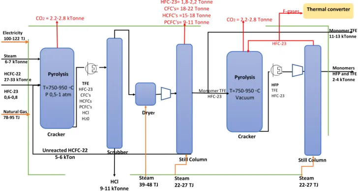
monomer, used mainly to produce copolymers or make adjustments to the homopolymer's physical properties (Drobny, 2009). Similarly, HFP can be produced by different chemical routes. One of them is by pyrolysis of TFE and trifluoromethane (HFC-23). The next diagram represents an overview of the production process of monomers TFE and HFP, including the main feedstocks amount, energy inputs, and GHG emissions. The black arrows represent main raw materials and products; red arrows are GHG flows, and orange arrows energy inputs.
Figure 3 General Production Process of Monomers HCFC-22 27-33 kTonne HFC-23 0,6-0,8 Pyrolysis T=750-950 ◦C P 0,5-1 atm Steam 6-7 kTonne TFE HFC-23 CFC's HCFCs PCFC's HCl H20 Scrubber Still Column HCl 9-11 kTonne Monomer TFE Cracker HFC-23= 1,8-2,2 Tonne CFC's= 18-22 Tonne HCFC's =15-18 Tonne PCFC's= 9-11 Tonne Dryer Pyrolysis T=750-950 ◦C Vacuum Cracker Still Column Unreacted HCFC-22 5-6 kTon HFC-23 Monomers HFP and TFE 2-4 kTonne Monomer TFE 11-13 kTonne HFC-23 HFP TFE HFC-23 Electricity 100-122 TJ Natural Gas 78-95 TJ Steam 22-27 TJ Steam 22-27 TJ Steam 39-48 TJ CO2= 2.2-2.8 kTonne CO2= 2.2-2.8 Tonne Thermal converter F-gases
TFE (Tetrafluoroethylene)
The pyrolysis of HCFC-22 (CHClF2) is a gas phase process that takes place at high temperatures (around 750-950 °C) and atmospheric or sub-atmospheric pressures (0.5-1.2 atm), in a flow reactor, at very short contact times (2-3 sec.) (Drobny, 2009). Because of HFC-22 pyrolysis's endothermic features, the reaction requires heat supply (Ebnesajjad, 2015). Equation 6 is the pyrolysis's general reaction to produce TFE in which HCl is produced as a by-product. A decrease in the partial pressure of HCFC-22, adding an inert gas or water vapor as a diluent, leads to higher TFE production rates.16 (Ebnesajjad, 2015). Different by-products are obtained from the pyrolysis, such as HCl and halogenated compounds like HFP (C3F6), perfluorocyclobutane, and perfluoroisobutylene (C4F8). Process condition adjustments can modify the output composition.
2𝐶𝐶𝐶𝐶𝐶𝐶𝐶𝐶𝐻𝐻2 ↔ 𝐶𝐶𝐻𝐻2 𝐶𝐶𝐻𝐻2 + 2𝐶𝐶𝐶𝐶𝐶𝐶 (eq. 6)
The output gas stream, composed mainly of TFE, HFP, by-products, and also unreacted HCFC-22, is then cooled and passed through different separation steps to increase the monomers' purity. Separation steps include removing HCl and HF by scrubbing and washing, using water, and basic solutions. Further, a drying process is applied, using a drying agent like calcium chloride and sulphuric acid (Drobny, 2009). The gas stream is then compressed and distilled to recover the unreacted HCFC-22 (Ebnesajjad, 2015).
Strict safety measures are required for the handling of TFE, considering its instability and high flammability. TFE polymerizes spontaneously at ambient temperature, and in contact with air, it produces explosive peroxides. Also, even when air is removed, TFE contact with a hot metal surface or a spark from static electricity can generate explosions; an inhibitor, such as terpene, can help avoid spontaneous reaction (Ferrero and Shenton, 2017). Because of that, Chemours uses dichloromethane (DCM) as a coolant during the production of
monomers to maintain a very low temperature (around -35°C).
HFP (Hexafluoropropylene)
HFP can be produced through the same pyrolysis reaction of HCFC-22 to produce TFE or through pyrolysis of TFE and HFC-23. This last method takes place at temperatures below 900 °C and longer residence time. Due to the endothermic features of the pyrolysis of HFC-23 and the exothermic dimerization of TFE, a heat balance is achieved through temperature controls to maintain safe reaction conditions (Ebnesajjad, 2015). The output gas stream passes through some separation steps like distillation, and then, the unreacted TFE and HFC-23 are recycled. In the case of Chemours, a closed-loop system of HFC-HFC-23 is operating in the monomers plant. HFP is very stable, so it does not autopolymerize and can be stored in a liquid phase without using an inhibitor (Moore, 2006).
2.1.4 Polymers and elastomers production
PTFE (Polytetrafluoroethylene) Production
PTFE, under the brand Teflon™, is a homopolymer of TFE. Homopolymerization takes place in the gaseous state, at moderate temperatures (60-90°C) and elevated pressures (15-35 atm), via free radical polymerization. This exothermic reaction occurs in an aqueous medium using initiators that are soluble in water (Drobny, 2009).
(eq. 7)
16 Le Chatelier’s principle anticipates that changes in concentration, volume, temperature or partial pressure,
Chemours has three batch production lines for dispersion and fine powder PTFE and granular PTFE. In the dispersion and fine powder production lines, an aqueous dispersion is formed, with a fluorinated surfactant and moderate agitation of the mixture. The agitation is relevant to remove heat from the reactor. Depending on the finishing steps, the final product can be the dispersion or the fine powder (Ebnesajjad, 2015). In the first case, the concentration of solids is increased by evaporation or thermal concentration. In the second case, a mechanic separation process removes the fine powder from the dispersion, which is later dried.
In the granular production line, a suspension process takes place, with an active agitation system of the mixture and using small amounts or even no surfactant. The reactors need to have an external heating/cooling system to heat the reactor at the beginning of the reaction and remove the heat generated by the exothermic reaction when the polymerization is progressing (Ebnesajjad, 2015). In this process, the formed product is water with unregular polymer particles. The two main finishing operations are the removal of water and the size reduction of particles. Depending on the final resin (pellets, divided resins), grinding and agglomeration can be used. These operations may require the use of fluorinated surfactants.
FEP (Fluorinated Ethylene Propylene) Production
FEP, also branded as Teflon™, is a copolymer of TFE and HFP, which has similar properties to PTFE. The conditions for the copolymerization reaction are comparable to the conditions described for the dispersion production of PTFE. The mix ratio between the comonomers is determinant to control the polymer's composition and its molecular weight. Usually, the FEP composition requires only 5mol% of HFP (Teng, 2012).
(eq. 8)
FKM Elastomers (Chlorotrifluoroethylenevinylidene fluoride) Production
FKM, under the brand Viton™, is a fluorocarbon elastomer produced by the free radical emulsion copolymerization of the monomers vinylidene fluoride (VDF), TEF, and HFP. VDF is a flammable gas at room temperature and can be explosive in contact with air.
Fluoroelastomers are copolymers of different monomers; thus, the monomers reactivity ratios determine the polymer's final composition. The polymerization reaction is exothermic and takes place at pressures around 120 atm, using an initiator (Moore, 2006). Chain
transfer agents, such as methanol, are used to regulate the molecular weight of the polymer. Typically, suspension polymerization is used for VDF/HFP/TEF polymerization. The product of the reaction is a latex that is coagulated by adding salt or acid. Subsequently, the coagulated latex goes to the filtration, washing, and drying process (Drobny, 2009). Fluorinated
surfactants are also used in this process.
The diagrams below represent the three main polymerization processes, including the main energy inputs and the main feedstock amounts. In this step of the process, there are no direct GHG emissions.
Figure 4 General Production Process of Polymers and Elastomers T= 60-90 ◦C P=15-35 atm Liquid Phase CopolymerizationBatch Reactor HomopolymerizationBatch Reactor Monomer TFE 8-10 kTon PTFE (Teflon™) = 7-8 kTonne FEP (Teflon™) = 2-3 KTonne
Copolymerization Batch Reactor Monomer VDF = 2,0-2,5 kTonne FKM (Viton™) Water,Initiator, Surfactants Water, Initiator, Surfactants Water, Initiator, Surfactants, additives T= 80-100 ◦C P=30 atm Liquid Phase T= 40-60◦C P=120 atm Liquid Phase Degasser Dispersion blender
Monomers to recovery= 1 kTonne
PTFE (Teflon™)
FEP (Teflon™)
FKM Elastomers (Viton™)
FKM (Viton™) = 3,5-4,5 kTon
Monomer TFE= 1-2 kTonne
Monomers TFE and HFP= 1 kTonne
Monomers HFP and TFE =4,5-5,5 kTon Dryer Electricity= 37-46 TJ Steam = 103-126 TJ Steam = 31-38 TJ Dryer Steam = 6-8 TJ Finishing H20 PTFE Electricity= 20-25 TJ FEP Finishing Processes H20 2-3 kTonne 3-4 kTonne Electricity= 35-43 TJ Steam = 52-64 TJ Steam = 10-12 TJ
2.1.5 Main Material Flows
Material flow estimations are presented in the table below, based on some studies about the kinetics of fluorination of chloroform (Santacesarea et al., 1989), the industrial production of HFC-23 as a by-product during HCFC-22 production (Irving and Branscombe, 2000), and the pyrolysis of HCFC-22 (Chinoy and Sunavala, 1987), in addition to the information shared by Chemours and public information about imports and trading (CBS, 2020).
Table 7 Chemours main mass flows
(CBS,2020; EMJV, 2018; own calculations and estimations)
Section Plant Main Input (Kt/year) Amount Main Output (in bold letters) (Kt/year) Amount
HCFC- 22 Production Plant-Fluorination Reactor HF 14-17 HCFC-22 27-33 Chloroform 42-51 HFC-23 0.8-1.2 HF 7.2-8.8 HCl 21-25 Total 56-68 56-68 Monomers Production Plant
HCFC-22 27-33 (TFE and HFP) Monomers 13-17
HCFC-22 (to recycle) 5-6 HCl 9-10 Total 27-33 27-33 PTFE Production Plant
Monomers (TFE) 8-10 PTFE 7-8
Unreacted monomers (to recycle) 1-2 Total 8-10 8-10 FEP Production Plant Monomers (TFE+HFP) 3-4 FEP 2-3 Unreacted monomers (to recycle) 1 Total 3-4 3-4 Elastomers Production Plant Monomers
(TFE+HFP) 2-3 Elastomer Viton™ 3.5-4.5
VFD 2.0-2.5 monomers Unreacted
(to recycle) 0.5-1.0
Total 4.0-5.5. 4.0-5.5
Whole Plant Elastomers (PTFE, FEP Viton) Total Final Polymers and 12.5-15.5
2.1.6 Main Energy Consumption
Based on the Elektronisch Milieujaarverslag (2018) document and the energy overview 2018, shared directly by Chemours, the main energy consumption discriminated by energy carrier in each step of the process was estimated and is described in the next table.
Table 8 Main Energy Consumption
(EMJV, 2018 and Chemours energy overview, 2018)
The greatest demand for electricity comes from two refrigeration machines used to keep a low temperature (-45°C) to guarantee the proper safety conditions to produce and handle TFE. TFE polymerizes spontaneously at ambient temperature due to its instability and high flammability and can generate explosions; thus, it requires strict safety measures (Ferrero and Shenton, 2017). Electricity to operate these refrigeration machines represents around 20% of the total electricity consumption.
The back-up steam boilers are the largest natural gas users, with around 52% of the total consumption. The other main consumption comes from two furnaces used for the pyrolysis process in monomers' production and the thermal oxidizer used in the F-gas thermal treatment.
PTFE plant uses almost 30% of the steam, including dryers, reactors, and heat exchangers; then, the second largest users are the distillation towers for the purification of HCFC-22 and monomers, being around 25%. The third-largest use is from the HCFC-22 plant, including heat exchangers, dryers, and the reactor. Then, there is the consumption of the other plants (monomers and the other polymers).
According to literature, the average energy consumption in the monomer TFE production process is 43 GJ/tonne (Hintzer and Schwertfeger, 2014). Using these numbers and based on an estimation of monomers production between 13 and 17 kt, it could represent an energy consumption around 560-731 TJ/year. Based on the table above, Chemour's energy consumption for monomers production is around 442 TJ/year (HCFC- 22 and monomers process), which means 26-34 GJ/tonne.
17 Electricity produced by the CHP in 2018.
Section Plant Electricity (TJ) Natural Gas (TJ) Steam (TJ) Total (TJ)
Input
Steam imports (HVC and DuPont
residual heat) -328 -328
Total Input -328 -328
End-use
Steam Production -4717 122 -106 -31
HCFC- 22 Production Plant 32 0 121 153
Monomers Production Plant 111 87 91 289
PTFE (Teflon™) Production Plant 42 0 148 190
FEP (Teflon™)Production Plant 23 17 40
FKM elastomers (Viton)
Production Plant 39 56 95
Thermal Converter 24 24
Others (CTW circulation pump) 44 44
Net end use/ consumption 245 294 328 804 Total balance 245 294 0 538
2.2 DuPont
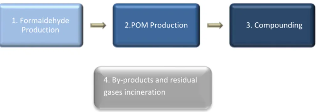
The DuPont process has three main steps: catalytic oxidation of methanol to produce formaldehyde (Formox process), formaldehyde polymerization to POM, and compounding (melting the polymer and mixing with additives to produce granules). Compounding is based mainly on electricity for the extruder and the mixing motor. There are also some heating and cooling steps in this part of the process.The main processes that take place at DuPont are illustrated in the diagram below:
2.2.1 Formaldehyde Production
Formaldehyde is produced at the industrial level from methanol through two main routes: the air-deficient process or silver contact and the Formox process, which implies an excess of air. DuPont Dordrecht uses the Formox process, which is the partial oxidation of the vapor phase methanol over a metal oxide catalyst. This reaction is highly exothermic, and the heat generated drives the dehydrogenation of methanol (Bahmanpour et al., 2014). DuPont uses the reaction heat to produce steam.
(eq. 11)
Fresh and recycled methanol is combined with an airstream, and the mixture is vaporized at 115°C. Air is used in excess to keep the methanol/air ratio below the explosion limits (Wells, 2020). Then, the gas is mixed with steam, reaching the reaction temperature. The mixture passes through a catalyst bed reactor, where the oxidation of methanol occurs, and
formaldehyde is produced (Elliott et al., 1996). Iron/molybdenum or vanadium oxide are the main catalysts used in this process. Methanol is practically totally converted at temperatures around 270 °C – 400 °C and atmospheric pressures. However, oxidation of formaldehyde to carbon monoxide increases at temperatures above 470 °C. Typically, the conversion of methanol is between 97% and 99%, and the total yield is around 88-91% (Bahmanpour et al., 2014).
(eq. 12) 1. Formaldehyde
Production 2.POM Production 3. Compounding
Figure 5 DuPont Main Processes
4. By-products and residual gases incineration
According to some researches, the reaction could take two different routes, depending on the surface heterogeneity of the molybdenum oxide catalyst. Methanol suffers dehydration and produces dimethyl-ether (DME) on the hexagonal surface; simultaneously, methanol partially oxidizes to produce formaldehyde, which is the main product. Other studies suggested that by using iron oxide as a catalyst, complete oxidation of methanol is achieved, and high amounts of CO2 are produced (Bahmanpour et al., 2014). According to Ivanov and Dimitrov (2008)., the main source of CO2 emissions is DME oxidation. The conversion to CO2 can be approximately 0.2-0.4%. In the following equation scheme, there is a representation of the different oxidation reactions that occur and the main products and by-products.
(eq. 13) Scheme of reactions for the oxidation and dehydration of methanol (Ivanov & Dimitrov, 2009)
The reactor's product stream at around 280 °C is immediately cooled down to about 110 °C in a heat exchanger, and then it is fed to an absorption column (Elliott et al., 1996). The amount of water ad at the top of the column is a control parameter of the formaldehyde concentration (Bahmanpour et al., 2014). An aqueous solution of approximately 55% formaldehyde, known as formalin, is obtained from the absorber's bottom. The gases from the top of the absorber are scrubbed with water and later burned (Wells, 2020). The residual process gases from formaldehyde production require a purification process, which is also exothermic and produces heat (Mursics et al., 2020).
For this purpose, DuPont Dordrecht has an emission control system (ECS) unit. There, the off-gas from the absorber, containing by-products from formaldehyde production, are catalytically oxidized. These by-products are mainly CO, N2, O2, methanol, and DME, which are converted to CO2 in the ECS (Gammelgaard,2018). The ECS unit also generates heat to produce steam (DuPont direct communication, 2020). Steam could also be used to produce electricity.
Over time, important process optimization and improvements have taken place to increase the production yield and the steam production and to reduce the CO selectivity and energy consumption. Pressurization at 0.3-0.5 bar, the prevaporization of methanol, catalyst innovation, and turbocharger use to reduce power consumption are part of the process improvements (Wells, 2020).
According to literature, the amount of methanol required to produce 1 tonne of formaldehyde at the industrial level can be around 1.16 tonnes (Wells, 2020); and the average steam amount produced is about 750-800 kg/tonne, which is driven by the methanol concentration in the inlet stream to the reactor (Andersson et al. 2016).
The next schematic diagram illustrates the main Formox process steps, including the ECS unit.
During the formaldehyde industrial process, the main sources of emissions are the ECS unit and some fugitive emissions from tanks and pipelines (Elliott et al., 1996).
DuPont has an up to date energy efficiency plan and a function called the “energy champion” to look for future developments regarding energy consumption reduction and optimization. The role focuses on the analysis of the consumption of energy and flows of residual heat. Heat recovery is an essential aspect of the energy strategy due to the high amounts of heat generated in formaldehyde production and the incineration of by-products and residual process gases. The formaldehyde plant produces steam, which is later used in the Delrin® chemical plant. Besides, the ECS unit generates heat to produce steam as well.
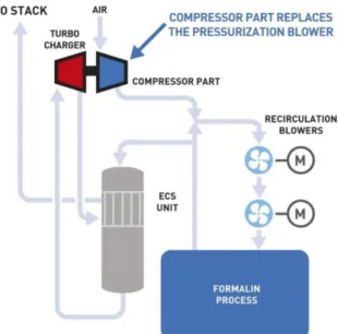
As illustrated in figure 15, a turbocharger uses the ECS gas output energy to supply air to the formaldehyde plant, using around two-third of the energy required using an electric blower (Svensson, 2012).
Figure 7 The turbocharger concept (Gammelgaard, 2018)
Consequently, and because of the energy integration and the implementation of different projects, like insulation to avoid heat loss, the formaldehyde factory's heat consumption is negative (DuPont, 2018). Moreover, during the incineration of waste gases from other processes, the heat released is used to produce steam, which is used in other parts of DuPont and Chemours processes. The total steam produced from Formox process and the incineration furnace is around 650-700 TJ (DuPont information and own calculations).
2.2.2 Main Material Flows
The table below shows some general estimations of inputs and outputs for an annual formaldehyde production of 100 kt/year. This analysis elucidates, to some extent, the generation of CO2 emissions in this part of the process. According to the literature review, CO2 is produced mainly due to other secondary oxidation reactions, such as dimethyl ether (DME) oxidation.
Table 9 Mass Estimations of Formaldehyde Production-Oxidation Reactor
INPUT OUTPUT kt kt Methanol 116 Formaldehyde 100 N2 90 H20 101 O2 298 Unreacted methanol 2 Recycled N2 1,191 CO 5 Recycled O2 120 N 1,489 Recycled H20 34 O2 150 HCOOH 2 CO2 1 Total 1,849 1,849
Table 10 Mass Estimations of Formaldehyde Production-Absorber
INPUT OUTPUT
kt kt
Formaldehyde HCHO 100 Formaldehyde 100
Bottom H20 101 H20 152 Unreacted methanol 2 CH3OH 2 HCOOH 2 HCOOH 2 CO 5 CO 5 Top N 1,489 N 1,489 O2 150 O2 150 CO2 1 CO2 1 Solvent (Water) 103 H20 52 Total 1,951 1,951
2.2.3 POM Production and Finishing Process
Formaldehyde produced from the formox process described above is the monomer to produce polyoxymethylene (POM). The general production process of POM can be divided into four different steps: monomer purification, polymerization, end-capping, and finishing. The aqueous formaldehyde solution passes through a reactive extraction process, using alcohol to dehydrate the hemiformal/water mixture and form hemiformal (Masamoto et al., 1994). Then, the hemiformal is heated to release the formaldehyde. The following equations illustrate these separation processes:
(eq. 14 and 15)
Next, the formaldehyde gas monomer is polymerized by anionic catalysis; a deactivator, such as an organic or inorganic base, is added to finish the polymerization and suppress other reactions (Lüftl & Chandran, 2014). The resulting polymer (POM) is stabilized using acetic anhydride as a chain transfer or end-capping additive. The stable POM goes to the extrusion plant to produce the Delrin® final product grains.
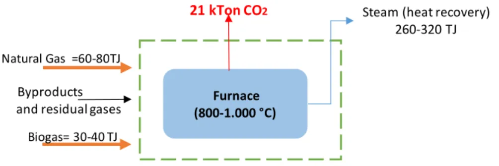
All the by-products and residual gases from the POM production are sent to incineration in the furnace, where the heat released is used to produce steam.
2.2.4 Main Energy Consumption
Based on Elektronisch Milieujaarverslag (2018) document, literature review, and general information shared by DuPont, some calculations and assumptions were made to determine DuPont's energy consumption. It was then discriminated by energy carrier in each step of the process and described in table 11. The highest energy demand for DuPont is related to steam consumption. This steam is mainly used in the concentrator, the pyrolysis,
stabilization, and dehydration processes (polyoxymethylene production), and also in the drying operations (finishing and compounding processes) (DuPont direct communication,
2020). Natural gas is used to operate the furnaces and the back-up boiler. The Delrin® compounding factory uses energy mainly in the form of electricity to run the extruders.
According to the literature review, DuPont information and estimations, steam production from the furnace heat recovery could be around 260-320TJ. This steam is used to supply the process's energy requirements, reducing DuPont's net energy consumption.
Table 11 Main Energy Consumption (Estimations from Elektronisch Milieujaarverslag, 2018 and Dupont direct communication)
Section Plant Process/Technologies Electricity (TJ) Gas (TJ) Natural Steam (TJ) Biogas (TJ) Total (TJ)
Input
Steam imports (HVC) -708 -708
Total Input -708 -708
End-use
Steam Production (backup boiler) 350 -280 70
Process residual heat18 -700 -700
Water treatment19 -31 -31 Formaldehyde Production Methanol Evaporator Concentrator 67 510 577 POM Production Dehydration of hemiformal Pyrolizer Stabilizer 51 600 651 Compounding Centrifuge Dryer Extruder 135 390 525
Process by-products and residual
gases incineration Furnace 74 31 105
Others (cooling) 85 85
Net end use/consumption 0 338 424 52120 0 1283
Total balance 338 424 -188 (residual heat sent to Chemours) 0 574
The next schematic diagrams represent DuPont processes, including the main flows of energy (orange arrows) and the main material flows (black arrows). The red color represents the main CO2 emissions.
18 The calculated steam production from residual heat includes heat recovery from formox process and from
the incineration of by-products and residual gases.
19 Biogas is produced in the water treatment throughout biological processes
20 Net end use of steam corresponds to the total estimated consumption of steam minus the steam generated
1. Formaldehyde Production
CH2O (40-50% water) 80-100 kTonne Water=120-140 kTonne 1 kTonne CO2 Controlled oxidation of methanol (260-390 °C) CH3OH 100-120 kTonne O2 (Air) Steam= 460-560 TJ Electricity 130-160 TJ Water (absorber) 80-100 kTonne ECS unitSteam (heat recovery) 360-450TJ CO20,4-0,5 kTonne CH2O CH3OH DME
Plastic Extrusion;
Drying
3. Compounding
Stabilizer
Delrin® Granes
80-100 kTonne
Electricity 120-150TJSteam= 350-450 TJ
Reactive Extractionof Formaldehyde Cracking of Hemiformal (170°C)
Polymerization of formaldehyde to POM R-O-(CH2O)K-H (Hemiformal) 90-110 kTonne Pure CH2O (vapor) 90-110 kTonne POM powder (thermally unstable) 80-100 kTonne Acetylation Acetic anhydride Base Alcohol (Liquid) Steam 540-660 TJ Electricity 40-60 TJ Water 120-140 kTonne Anaerobic water purification
POM powder (thermally stable) 80-100 kTonne 2. POM Production
Regarding CO2 emissions, besides the emissions from the production reaction of
formaldehyde, there are other sources. 21 kt/year are emitted in the incineration process. This amount includes 4 kt from natural gas combustion, 3 kt from biogas combustion, and 14 kt/year from the residual gases and by-products combustion. Additionally, natural gas combustion, mainly for steam production generates approximately 17 kts/year (Estimations from NEA, 2018, and EMJV, 2018). This will be further developed in chapter 4.
During DuPont's processes, there are other emissions than GHG; however, considering the MIDDEN project's scope, the analysis is only focused on GHG emissions.
2.3 Dow
Extrusion is one of the most used techniques to process plastics, and it is also used as a basis for other processing techniques. However, some applications require to modify the polymers, using peroxides, halogens, or grafting techniques, to improve some properties such as thermal or mechanical stability, chemical resistance, and compatibility. Reactive extrusion is used to modify and process a polymer simultaneously (Isac, 2001).
Furthermore, it allows the production of polymers with functional groups, like copolymers with carboxyl groups. The direct polymerization process cannot produce these copolymers. Grafting is the reaction between a molten polymer with a monomer or a mix of monomers to make grafts to the polymer backbone. It means that one polymer grows as branches on another polymer (Rudin and Choi, 2013). The reactivity and molar ratio of the monomer and polymer, the amount of initiator, and the process temperature are some of the parameters that determine the graft chain length. The extruder acts as a pressure vessel, with
temperature and residence time control, and venting of unreacted monomer and by-products.
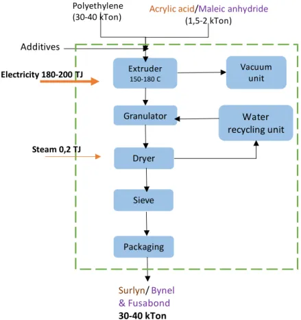
Polyethylene can be grafted with acrylic acid, using a crosslinking peroxide such as DCP (dicumyl peroxide) in an extruder reactor at 180 °C. Also, grafting of maleic anhydride with polyethylene is another example of reactive extrusion, using free-radical initiators, like peroxides. In the Dordrecht plant, Dow uses acrylic acid in one production line to produce resins under the name of Surlyn™, and maleic anhydride in the other one to produce resins under the brands Bynel™ and Fusabond™. The amount of maleic anhydride is around 1-5% of the total polymer, and the amount of DCP can be about 2-6% of the maleic anhydride amount. In the next diagram, there is a schematic representation of Dow processes in Dordrecht, including the main flows of energy and materials:
Furnace (800-1.000 °C)
4. Furnace -Incineration byproducts and residual gasses
Natural Gas =60-80TJ
Biogas= 30-40 TJ
21 kTon CO2
Byproducts and residual gases
Steam (heat recovery) 260-320 TJ
Figure 9 Scheme of Dow processes and main flows of energy and materials (Shared directly by Dow)
2.3.1 Main Energy Consumption
Dow operation at Dordrecht is relatively small, and the main energy demand is electricity to operate the extruders for the two production lines and a small amount of steam, provided by Chemours, for drying operations. In table 6 above (presented on page 15), there is a
summary of Dow's main energy consumption in the Dordrecht site. Extruder 150-180 C Granulator Dryer
Water
recycling unit
Sieve Packaging Vacuum unit Polyethylene(30-40 kTon) Acrylic acid(1,5-2 kTon)/Maleic anhydride
Additives
Surlyn
/
Bynel
& Fusabond
30-40 kTon
Steam 0,2 TJ Electricity 180-200 TJ3 Dordrecht Chemical
Cluster products and
applications
This section contains information about the products manufactured in Dordrecht by each company, their main raw materials, applications, market insights, and the main sustainability trends.
3.1 Chemours: Fluoroproducts Market Overview
Fluoroproducts are produced from mined fluorite and include fluorocarbons, fluoropolymers, and surfactants. The development of the automotive and electronics industry and the accelerated industrialization have promoted the growth of the fluoroproducts market (Ahuja and Singh, 2018). One of the main segments of fluorocarbons is the refrigerants market, in which the largest amount corresponds to HCFC-22. China leads the production globally, with 418 kt/year produced in 2016, followed by The United States, with a reported amount of 135 kt/year in 2011. In 2015, the European Union had a production of around 120 kt/year, with HCFC-22 being the main gas produced (Abdelaziz, et al., 2020). Because this substance is part of the ozone-depleting substances (ODS) regulated by the Montreal Protocol, its consumption is decreasing, and it is in a phase-out process. Europe prohibited the use of HCFC-22 for emissive applications (refrigerants). However, its use as a feedstock (mainly to produce fluoropolymers) is not restricted.
Furthermore, the emissions of HFC-23, as a by-product of the HCFC-22 production process, are strongly regulated (Abdelaziz et al., 2020). In the case of The Netherlands, HCFC-22 production is only allowed as a feedstock.
3.1.2 Fluoropolymers
In the 1930s, during some investigations about fluorinated refrigerants, by accident a scientist from DuPont in the USA, discovered the polymerization of TFE into PTFE. PTFE's outstanding properties were later recognized to meet the needs of having a polymer able to resist highly corrosive conditions in the fabrication of the first atomic bomb during the second world war. In 1946, DuPont de Nemours started PTFE commercialization under the brand Teflon™ (now owned by Chemours) (Hintzer & Schwertfeger, 2014).
Fluoropolymers are polymers with only carbon and fluorine in the polymer backbone. The strength of the carbon-carbon bond and the high stability of the carbon-fluorine bond explain these polymers' unique properties. The replacement of hydrogen by fluorine in a polymer increases the service temperatures, reduces flammability, and gives low surface energy, which implies nonstick properties, a low coefficient of friction, and a low solubility in hydrocarbons. Furthermore, it offers high electrical and optical properties (Smith et al. 2014). The next table summarizes the main applications and properties of fluoropolymers.
Table 12 Fluoropolymers: Key Properties and Main Applications (Ebnesajjad, 2014)
Industry/Application
area Key Properties Typical uses
Chemical processing
Chemical resistance Good mechanical properties Thermal stability
Cryogenic properties
Gaskets, vessel liners, valves, and pipelines
Electrical and
communication
Low dielectric constant High volume/surface resistivity High dielectric breakdown voltage Flame resistance, thermal stability Low refractive indices
Wire and cable insulation, connectors, optical fibers
Automotive and office equipment
Low coefficient of friction Good mechanical properties Cryogenic properties Chemical resistance
Seals and rings in automotive power steering, transmission, and air-conditioning. Copier rollers. . Fuel management systems
Houseware
Thermal stability Low surface energy Chemical resistance
Cookware coatings and food processing equipment covering
Medical
Low surface energy Stability
Excellent mechanical properties Chemical resistance
Cardiovascular grafts, heart patches, ligament replacement, intravenous infusion membranes Architectural fabrics/films
Excellent weatherability Flame resistance Low surface energy
Coated fabric and films for building and roofs, front/backside films for solar applications
3.1.3 Fluoropolymers Main Raw Materials
Fluorspar
Fluorspar is one of the main feedstocks for hydrofluoric acid (HF) production, a main input at Chemours Dordrecht. It is a natural mineral, which is mainly found in mines located in China, Mexico, Mongolia, South Africa, and Namibia. Although Europe still has some fluorspar mines, the viable ones have reduced over time (Eurofluor, 2019). Contrary, China has the third position of fluorspar deposits globally and is one of the main exporters, giving this country a critical competitive advantage in the fluoroproducts market (Po, 2017). Fluorspar price, but mostly its availability, drive the prices of fluoropolymers.
Fluorspar has different grades, but the acid grade is the most widely used, i.e., hydrofluoric acid (HF). This grade is produced by the reaction of fluorspar and sulphuric acid. Because of the highly corrosive potential of hydrofluoric acid, there are strong international regulations to meet safety criteria during production, handling, storage, and use of this product, especially related to the materials used for transportation and packaging. Hydrofluoric acid (HF) is transported by rail from Germany. HF prices are around €1,700/tonne (CBS, 2020).
Chloroform
Chloroform, or trichloromethane, is a volatile solvent. Its main use is to produce HCFC-22, which is used to produce mainly fluoropolymers and also refrigerants. As reported by ICIS outlook in 2002, Europe's demand for this product has been reduced by the restriction over HCFC-22 production in the refrigerants industry due to the Montreal Protocol. Nevertheless, the growth of the fluoropolymers market has compensated for that gap in demand. In