structures
A literature review on low-crested and submerged
Academic year 2019-2020
Master of Science in Civil Engineering
Master's dissertation submitted in order to obtain the academic degree of
(Universitat Politècnica de València, Spain)
Supervisors: Prof. dr. ir. Peter Troch, Prof. dr. ir. Josep Ramon Medina Folgado
Student numbers: 01404272, 01408578Preface
We would like to express our deep gratitude to professor Peter Troch and professor Josep Ramon Medina Folgado for their guidance, encouragement and help. Especially when the Covid-19 pandemic caused the closure of the research laboratory of Ports and Coastal Engineering of the Universitat Politècnica de València, professor Troch and professor Medina guided us towards a new research objective.
The model tests were executed by multiple people and therefore we would like to thank Enrique
Ripoll Dominguez(lab supervisor), Victor Brisa and Sergio Lozano. The measurements of the
layer coefficient would not have been possible without the proper equipment for which we thank Carlos Alonso, the lab technician. Furthermore, a word of thanks goes to Riccardo Centi for sharing his results of the numerical modelling with blender and providing us with a validation for our measurement.
Lastly, we wish to thank our parents for supporting us throughout the course of our studies as well as the University of Ghent and the Universitat Politècnica de València for providing us a challenging and enriching engineering program and giving us the opportunity to study abroad.
Ghent, 15th of June 2020 Karel De Keyser Elias Jacobs
The authors give permission to make this master dissertation available for consultation and to copy parts of this master dissertation for personal use. In all cases of other use, the copyright terms have to be respected, in particular with regard to the obligation to state explicitly the source when quoting results from this master dissertation.
Abstract
Sandy beaches all over the world are of great value due to their ecological importance. Moreover they are essential to the economy of many countries and their stability is often dependent on the health of adjacent coral reefs. Despite this great value of sandy beaches, coastal erosion is becoming a significant problem at many coastal sites. As the global sea level rises and extreme wave climate increases, coastal erosion threatens the marine health and economy in many places. Although coastal erosion is a natural process it is often intensified by manmade structures.
Low-crested and submerged structures are a possible solution to this problem, especially in touristic regions these types of structures are popular for shoreline protection as their visual impact is minimal. In many cases they have had promising results in coastal erosion mitigation. However, to the best of the authors’ knowledge, in current literature a clear classification and comparison between different types of low-crested and submerged structures is missing. This master thesis aims to make a profound literature research on these structures. This is done by presenting information on design methods, transmission properties, case studies, building methods and describing their advantages and disadvantages. A specific aspect of this study includes a new typology of low-crested structures, called homogeneous low-crested structures (HLCS). This new type of reef breakwater consists of very large, static-stability units which are re-usable, and for Cubipod HLCS lab tests were performed to determine the layer coefficient in function of the placement grid.
Subsequently, a comparison between all types of low-crested and submerged structures is made and a roadmap is drafted to guide the reader in the decision-making process for selecting a coastal defence structure with low visibility. Furthermore, an indication is given of knowledge gaps, as well as some innovative ideas.
It can be concluded that it is very difficult to dedicate one type of typology to a specific project as many variables are involved in the selection process. In general, the purpose, proximity of a rock quarry, available construction equipment and the environmental restrictions that need to be considered will be decisive as to which construction is most suited for a specific project.
Key words: Shoreline protection, low-crested structures, submerged structures, layer coefficient, Cubipod
A literature review on low-crested and submerged
structures
Karel De Keyser1, Elias Jacobs2
Supervisors: Prof. dr. ir. Peter Troch3, Prof. dr. ir. Josep Ramon Medina Folgado4
Abstract - Sandy beaches all over the world are of great value due to their ecological importance. Furthermore, they are essential to the economy of many countries. Despite this great value of sandy beaches, coastal erosion is becoming a significant problem at many coastal sites. As the global sea level rises and extreme wave climate increases, coastal erosion threatens the marine health and economy in many places. Low-crested and submerged structures are a possible solution to this problem. They are popular shoreline protection structures in touristic regions because of their low visual impact. In many cases they have had promising results in coastal erosion mitigation. However, to the best of the authors’ knowledge, in current literature a clear classification and comparison between different types of low-crested and submerged structures is missing. Therefore, this master thesis aims to make a profound literature review on these structures. A roadmap is drafted to guide the reader in the decision-making process for selecting a coastal defence structure with low visibility. Although the selection process is quite complex as many variables are involved, it can be concluded that the purpose of the structure, the proximity of a rock quarry, the availability of construction equipment and the environmental restrictions will be decisive as to which typology is most suited for a specific project.
Keywords - Coastal erosion, (homogeneous) low-crested structures, submerged structures, layer coefficient, Cubipod
I. INTRODUCTION
A large part of the world population lives near the coast and in many countries beach tourism is an important aspect of the economy. Therefore, sandy beaches are of great value and their quality and stability are crucial. Despite this, coastal erosion is a problem at many coastal sites and is increasing in magnitude due to climate change. The increase in extreme wave climate and global sea level rise, induces erosion and flooding of beaches [1]. Erosion and accretion of sandy beaches is a natural process that is influenced by several phenomena (and in most cases these phenomena are intensified by humans).
Several measures have already been applied throughout the last decades to improve the coastal situation. These measures can be divided in structural and non-structural solutions. Examples of structures that have been used to avoid coastal erosion, protect ports or stabilize river mouths are amongst others: groynes, seawalls, revetments and breakwaters.
In touristic regions however, a solution without intrusive visual character is preferred. On top of their low visibility, the
1 Masterthesis student, Faculty of Engineering, Ghent 2 Masterthesis student, Faculty of Engineering, Ghent 3 Professor, Faculty of Engineering, Ghent University
submerged character of such structures will allow a more natural water circulation which favours the ecosystem in the lee side. This thesis aims to classify various typologies of such low-crested and submerged coastal defence structures. Additionally, guidance is given regarding design, applicability and efficiency of these structures. A clear classification, based on the amount of wave overtopping, is presented in Figure 1.
Non-overtopped structures are built with their crest significantly above sea level so that there is almost never water going over the structure. Low-crested structures (LCS) have their crest approximately at sea water level (SWL) and are characterized by significant overtopping. Submerged structures have their crest below SWL and are overtopped by all waves. The wave breaking process still affects their stability whereas near-bed structures have a crest elevation low enough so that the structure is not affected by wave breaking [2].
Figure 1: Coastal defence classification based on level of overtopping according to Ciria et al. [2].
A diagram of how the two structures discussed in this thesis are further divided into different types is given in Figure 2. LCS are subdivided into three categories: traditional rubble-mound LCS, dynamically stable reef breakwaters and HLCS. Submerged structures are divided into broad-crested structures, geotextile sand containers (GSC), prefabricated concrete structures, artificial reefs and inflatable submerged structures.
Figure 2: Low-crested and submerged structures classification.
II. LOW-CRESTED STRUCTURES
A. Homogeneous low-crested structures
Homogeneous low-crested structures (HLCS) are constructed with one size of pre-cast concrete elements (for example Cubipod HLCS) or large rocks (rock HLCS). A cross-section of a 3-layer Cubipod HLCS is shown in Figure 3. The Cubipod unit is patented by the Universidad Politècnica de València (UPV) and licensed by SATO. It is designed to benefit from the advantages of the traditional cubic block and additionally correct some drawbacks by preventing face-to-face arrangement and by increasing friction. Currently the Cubipod elements are used as single or double-layer armour units in mound breakwaters.
Figure 3: Cross-section of a 3-layer Cubipod HLCS [3]. When Cubipods are used as armour layer on mound breakwaters it is suggested to construct them in a diamond-type placement grid [4]. However, for elements of a HLCS the placement procedure is different as the Cubipods are stacked in horizontal layers. Therefore, new types of placement grids were suggested and several rectangular and triangular construction grids were investigated [3].
A parameter that deserves special attention with HLCS is the layer coefficient as it will influence the crest height. In this thesis a new measurement method was developed to physically determine the layer coefficient for different placement grids. Results indicated that the coefficient of the first layer is very close to the theoretical value. Lower values were observed for the second layer and even smaller values for the third layer. However, from the third layer onwards the layer coefficient is approximately constant. A similar conclusion was drawn by Riccardo Centi who performed numerical measurements with the Blender Game Engine software [5]. As both methods gave
performed on Cubipod HLCS by the University of Mexico (UNAM) [3].
B. Different types of low-crested structures
Homogeneous LCS are categorized as a special type of LCS, and as already indicated in Figure 2 also rubble-mound LCS and reef breakwaters are categorized as such. Rubble-mound breakwaters have a multilayer cross-section typically with core, filter layer(s) and armour layer. Reef breakwaters on the contrary do not have this multilayer cross-section and are often described as nothing more than a pile of stones. This type of structure is dynamically stable, meaning that the cross-section is allowed to deform under extreme wave conditions.
Each of these structures have advantages and disadvantages and the specific boundary conditions will dictate which typology is most appropriate for a specific situation. Rubble-mound LCS and reef breakwaters were developed several decades ago, in times when the environmental impact was considered as less essential. Rubble-mound LCS have the advantage that they are widely applied and have proven their efficacy. Their construction process is well known to many contractors. The strength of a reef breakwater is the design simplicity and easy placement. However, because this structure is dynamically stable, the efficiency will degrade over time. The biggest downside of both structures is that during their construction a lot of suspended materials are produced which threatens local fringe communities. Additionally, these structures block an important part of the water flow towards the landward side. HLCS perform better with regard to these two environmental issues. If no quarry is nearby a HLCS can be made of concrete units. HLCS also perform better with respect to sustainability as dismantling is easier and the units are reusable.
III. SUBMERGED STRUCTURES
Submerged structures are, unlike low-crested structures, overtopped by all waves. These structures are not only built for shoreline protection, other purposes include surf and environmental enhancement. Five types of submerged structures were distinguished (Figure 2).
Broad-crested structures have a crest width larger than approximately 6 times the water depth and are most effective in tidal environments with frequent storm surges. These structures are however quite costly due to the large volume of quarry stones. Geotube core broad-crested structures might offer a solution.
Geotextile sand container submerged structures consist either of large geotubes or smaller individual sand containers. In both cases the structure consists of sand-filled geotextile bags. The construction cost of this type of structure is significantly less compared to rubble-mound structures. Geotextile bags are quite vulnerable and therefore covering them with armour stone (and thus using them as a core) might be a better alternative.
A third type of submerged structure is the prefabricated concrete one. By comparing case studies for several prefab concepts it could be concluded that they offer a relatively cheap
Artificial reefs are built to enhance environmental conditions, be it by safeguarding habitats of ecological interests or by providing attractive elements for marine life. Alternatively, these structures are built to enhance the surf conditions at certain places. Artificial surf reefs have only been applied in recent years and because of the lack of experience with them, mostly the expectations were not fulfilled.
Lastly, a promising type of structure is proposed: the inflatable submerged breakwater. Their successful past as dams and storm surge barriers suggests that these could offer a viable solution in shoreline protection. By increasing the internal pressure, the structures could be adapted to wave conditions present at that moment. This huge advantage makes them interesting in areas with large tidal differences or for surf enhancement. The main problem with present-day artificial surfing reefs is that these are only effective for very specific wave conditions. For a slightly different wave height or period their effectiveness reduces significantly. Inflatable structures might be effective for a wider range of wave conditions as their crest level is adaptable.
IV. CONCLUSION
A comparison between all common low-crested and submerged structures is made and a roadmap is drafted to guide the reader in the decision-making process for selecting a coastal defence structure with low visibility. Furthermore, an indication is given of knowledge gaps and certain innovative ideas are proposed.
The solution selection process is quite complex as many variables are involved. In general, the purpose, the proximity of a rock quarry, the available construction equipment and the environmental requirements that need to be taken into account will be decisive as to which typology is most suited for a specific project.
ACKNOWLEDGEMENTS
The authors would like to express their deep gratitude to Professor Peter Troch and Professor Josep Ramon Medina Folgado for their guidance, encouragement and help.
REFERENCES
[1] S. Vitousek, P. L. Barnard, and P. Limber, “Can beaches survive climate change?,” J. Geophys. Res. Earth Surf., vol. 122, no. 4, pp. 1060–1067, 2017. [2] Ciria, Cur, and Cetmef, The Rock Manual. The use of
rock in hydraulic engineering., 2nd ed. C683, CIRIA, London, 2007.
[3] J. R. Medina, I. Odériz, E. Mendoza, and R. Silva, “Hydraulic performance of homogeneous low-crested structures,” Coast. Struct. 2019., pp. 9–10, 2019. [4] J. R. Medina and M. E. Gomez-Martin, Cubipod
Manual 2016. Valencia: Universitat Politècnica de València, 2016.
[5] R. Centi, “Placement tests and Layer Coefficient of homogeneous cubipod mound breakwaters using a game engine (unpublished),” Valencia: Universitat Politècnica de València 2020.
Preamble
The initial purpose of this work was to analyse a new type of low-crested structure (LCS), called homogeneous low-crested structure (HLCS). In order to determine the hydraulic stability and wave transmission of this type of structure, model tests would have been performed in the wave flume at the laboratory of Ports and Coastal Engineering of the Universitat Politècnica de València (UPV). HLCS are made by stacking large rocks or concrete units. The first objective was to find several viable placement grids and model layouts, however these experiments are still ongoing. Once selected, small scale physical model tests would have been performed on these viable structures to investigate hydraulic stability and wave transmission. The original title of the thesis would have been “Analysis of Hydraulic Stability and Transmission of Cubipod and Rock Homogeneous Low-Crested Structures” and this work is part of the HOLOBREAK project.
However, due to the Covid-19 pandemic, UPV decided to close the lab, following the Spanish regulations. The wave flume model tests foreseen for March-April 2020 were not possible and only preparatory work such as determining the layer coefficient for several construction grids and calibrating the wave flume was executed. Therefore it was decided to change the scope of this master thesis.
As a literature review on LCS was already part of the initial work, it was decided to expand the literature study to a broader study on all types of low-crested and submerged structures. The preparatory work for the model tests could in this way also be included in the final work. This work might provide important insights for further research, be it in the HOLOBREAK project or elsewhere. With the information gathered in this literature study an attempt is made in providing a road map for engineers or practitioners in finding an optimal solution for their coastal problem. This preamble was written in consultation between the students and the promotors and is agreed upon by both parties.
Table of content
Preface ... i
Abstract ... ii
Extended abstract ... iii
Preamble ... vi
Table of content ... vii
List of Figures ... ix
List of Tables ... xiii
List of symbols and abbreviations ... xiv
1 Introduction ... 1
1.1 Coastal erosion problems ... 1
1.2 General approach ... 2
2 Coastal defences ... 4
2.1 Defence structures perpendicular to the shoreline ... 4
2.1.1 Groynes ... 4
2.2 Defence structures parallel to the shoreline ... 6
2.2.1 Seawalls ... 6
2.2.2 Revetments ... 7
2.2.3 Breakwaters ... 8
2.2.4 Detached breakwaters ... 8
2.3 Low-crested and submerged structures ... 9
3 Low-crested structures (LCS) ... 11
3.1 Introduction ... 12
3.1.1 Advantages and disadvantages ... 12
3.1.2 Wave interaction ... 12
3.1.3 Wave transmission and reflection ... 13
3.1.4 Design of LCS ... 15
3.1.5 Scour protection ... 16
3.1.6 Shoreline response to detached LCS ... 17
3.1.7 Environmental aspects ... 19
3.2 Rubble-mound LCS ... 20
3.2.1 Structural design ... 21
3.2.2 Wave transmission and reflection ... 24
3.2.3 Construction ... 25
3.2.4 Applications... 26
3.3 Reef breakwater ... 27
3.3.1 Structural design ... 27
3.3.2 Wave transmission and reflection ... 28
3.4 Homogeneous low-crested structures (HLCS)... 29
3.4.1 Introduction ... 29
3.4.2 Construction materials ... 30
3.4.3 Layer coefficient ... 35
3.4.4 HLCS model characteristics ... 40
3.4.5 Lab setup ... 45
3.4.6 Grid and layer-coefficient analysis ... 47
4.1 Introduction ... 52
4.2 Broad-crested submerged breakwaters ... 53
4.2.1 Introduction ... 53
4.2.2 Types of broad-crested breakwaters ... 54
4.2.3 Advantages and disadvantages ... 56
4.2.4 Structural design ... 56
4.2.5 Wave transmission and reflection ... 57
4.2.6 Shoreline response to submerged structures ... 58
4.2.7 Construction ... 59
4.2.8 Environmental aspects ... 61
4.2.9 Applications... 61
4.3 Geotextile sand containers ... 62
4.3.1 Introduction ... 62
4.3.2 Advantages and disadvantages ... 64
4.3.3 Construction ... 65
4.3.4 Structural design ... 66
4.3.5 Applications... 67
4.4 Prefabricated structures ... 69
4.4.1 Prefabricated submerged breakwater types ... 70
4.4.2 Applications... 72
4.4.3 Construction ... 75
4.4.4 Advantages and disadvantages ... 76
4.5 Artificial reefs ... 77
4.5.1 Introduction ... 77
4.5.2 Protection reefs ... 78
4.5.3 Production reefs ... 79
4.5.4 Artificial surf reefs... 82
4.6 Inflatable structures ... 85
4.6.1 Inflatable dams ... 85
4.6.2 Inflatable storm surge barriers ... 87
4.6.3 Inflatable submerged structures ... 89
5 A roadmap to design low-crested and submerged structures ... 91
5.1 Overview table ... 91 5.2 Synthesis ... 93 5.3 Decision trees ... 95 5.4 Future recommendations ... 98 6 Conclusion... 100 6.1 Summary ... 101 References ... 103
Annex A: Rock classification sample ... 110
Annex B: Location Wave gauges ... 111
Annex C: Test matrix... 112
List of Figures
Figure 1.1: Example of erosion along the Belgian coast ... 1
Figure 1.2: Accretion (a) and erosion (e) near a port on a sandy coast (van de Graaff, n.d.). 2 Figure 2.1: Scheme of interaction of groynes, waves, currents and shore (Pruszak, n.d.). .... 5
Figure 2.2: Impermeable timber Groyne in Bournemouth (Van Rijn, 2018). ... 5
Figure 2.3: Filled sheet pile groyne (Perdok, 2002). ... 6
Figure 2.4: Types of seawalls ( Mangor et al., 2017). ... 7
Figure 2.5: Examples of revetments (Mangor et al., 2017). ... 7
Figure 2.6: Most common types of breakwaters (Ciria et al., 2007). ... 8
Figure 2.7: Illustration of tombolo and salient (Burcharth et al., 2007). ... 9
Figure 2.8: Coastal defence classification based on level of overtopping (Ciria et al., 2007).10 Figure 2.9: Low-crested and submerged structures classification. ...10
Figure 3.1: Rubble-mound LCS cross-section (van der Meer et al., 2005). ...11
Figure 3.2: Dynamically stable reef breakwater cross-section (Ahrens, 1989). ...11
Figure 3.3: Homogeneous Cubipod LCS (Odériz et al., 2018). ...11
Figure 3.4: Energy transfer at submerged and emerged breakwater (Schoonees et al., 2019). ...13
Figure 3.5: Parameters that affect wave transmission (DELOS, 2002). ...14
Figure 3.6: The water-level components that contribute to coastal flooding (Vitousek et al., 2017). ...15
Figure 3.7: Scour protection apron and influencing parameters according to DELOS (2002). ...17
Figure 3.8: Detached breakwater and creation of salient (left) and tombolo (right) (Mangor et al., 2017). ...17
Figure 3.9: Aerial view of detached breakwaters at Sea Palling, Norfolk, UK (image from Google Maps). ...18
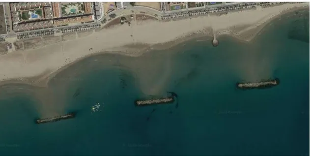
Figure 3.10: Detached rubble-mound LCS at Playa de Cubelles, Spain (image from Google Maps). ...21
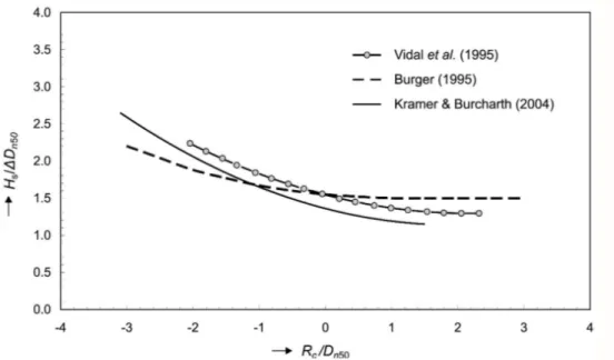
Figure 3.11: Comparison of stability formulae for low-crested structures for start of damage (Ciria et al., 2007). ...22
Figure 3.12: Division of armour layer in several segments (Ciria et al., 2007). ...23
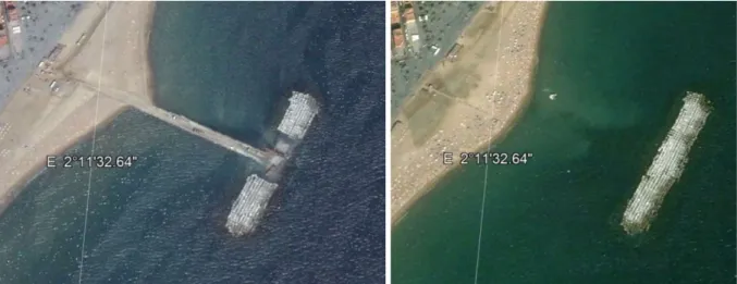
Figure 3.13: Detached breakwater near Barcelona during construction (left) and after construction (right) (image from Google earth Pro). ...26
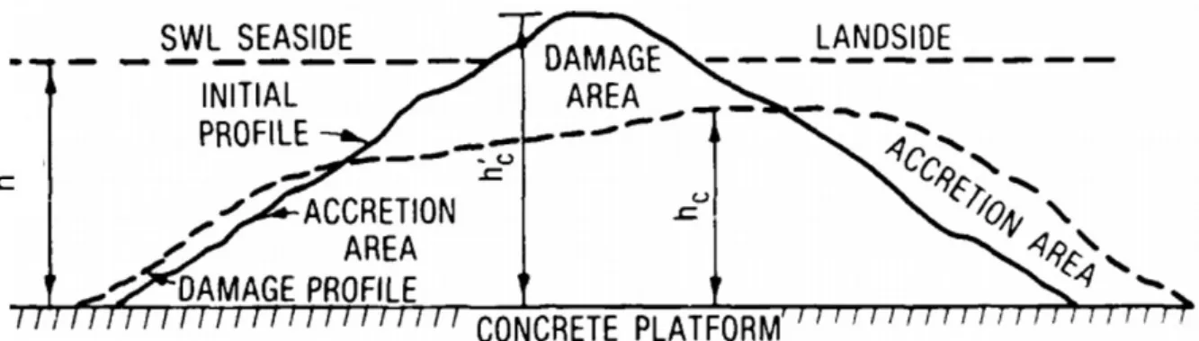
Figure 3.14: Cross-sectional view of initial and typical damaged reef profile (Ahrens, 1987). ...27
Figure 3.15: Cross-section of a 3-layer Cubipod HLCS (Medina et al., 2019). ...30
Figure 3.16 Use of Cubipods on the San Andrés breakwater in the port of Malaga (“San Andrés Breakwater - Port of Málaga,” n.d.). ...31
Figure 3.17 Use of pressure clamps (left) and characteristics of a Cubipod unit (Medina and Gomez-Martin, 2016) (right). ...32
Figure 3.18: Illustration of armour stone shape measurement systems (Ciria et al., 2007). ..33
Figure 3.19: Examples of different blockiness values (from left to right, BLc= 80%, 60% and 40%) (Ciria et al., 2007). ...33
Figure 3.20: System for limits of EU standard gradings (percentages of passing for heavy grading) (Ciria et al., 2007). ...35
Figure 3.21: Visual representation of the theoretical orthogonal thickness (Ciria et al., 2007). ...37
Figure 3.22: Layer thickness as a function of survey method (Latham et al., 2002). ...38
Figure 3.23: Calculation method of the layer coefficient for a Cubipod stacking. ...40
Figure 3.24: Example of triangular grid. ...41
Figure 3.25: Test setup for the determination of the layer coefficient. ...41
Figure 3.26: Positioning Cubipod in first layer (left) and placing of the plates (right). ...42
Figure 3.27: Calculation height of a Cubipod. ...43
Figure 3.28: Example of rock homogeneous LCS. ...44
Figure 3.29: Measurement of Yr-distance with an electronical digital caliper. ...44
Figure 3.30: Determination of the mass of the rock submerged in water. ...45
Figure 3.31: System of wave generation (left and middle) and passive absorption system (right). ...46
Figure 3.32: Wave flume of the Laboratory of Ports and Coastal Engineering (LPC) of the Universitat Politècnica de València (UPV). ...46
Figure 3.33: Freefall tests in the port of Alicante (left), simulation in blender (right). ...49
Figure 3.34: Placing the square plates upon the layer to be measured (second and fifth layer) in Blender. ...50
Figure 4.1: Overview of different types of submerged structures. ...53
Figure 4.2: Objectives of broad-crested submerged breakwaters (Yoshioka et al., 1993). ....54
Figure 4.3: Broad-crested submerged breakwater (Armono, 2004). ...54
Figure 4.4: Example of a broad-crested submerged breakwater with a geotube core for AmWaj project (Pilarczyk, 2003). ...55
Figure 4.8: Shoreline adjustment due to offshore reefs (Mead and Black, 1999). ...58
Figure 4.9: Current patterns and reef configuration (Yoshioka et al., 1993). ...59
Figure 4.10: Proposed submerged geotube breakwater layout for Amwaj Island (Fowler et al., 2002). ...60
Figure 4.11: Use of individual sand containers in a groyne (left), use of geotubes in a breakwater (right) (Hornsey et al., 2011). ...62
Figure 4.12: Submerged breakwater with GSC-core (Oumeraci and Kortenhaus, 2011). ...63
Figure 4.13: Submerged structure made out of geotextile bags (Parab et al., 2017). ...64
Figure 4.14: Placement of individual sand containers (Hornsey et al., 2011). ...65
Figure 4.15: Placement rail piles (left) and connecting with sand extraction equipment (right) (“Geotextile Bags, Tubes and Containers,” n.d.). ...66
Figure 4.16: Illustration of geotube placement (“Geotextile Bags, Tubes and Containers,” n.d.). ...66
Figure 4.17: Schematic diagram of 2D hydraulic stability of a geotube (Shin et al., 2016). ...67
Figure 4.18: Bursted geotube at Candolim Beach, India (Parab et al., 2011). ...68
Figure 4.19: New solution to control the erosion problem at Candolim Beach in India (Parab et al., 2011). ...68
Figure 4.20: Changes at Sigandu Beach, before (left) and after geotube installation (right) (Sulaiman et al., 2015). ...69
Figure 4.21: Diagram of P.E.P. Reef unit (Stauble and Tabar, 2003). ...70
Figure 4.22: Beachsaver unit photograph (Stauble and Tabar, 2003). ...71
Figure 4.23: Double-T sill and idealised response (Stauble et al., 2005). ...71
Figure 4.24: Typical prototype modular breakwater (Medina et al., 2007). ...72
Figure 4.25: Positioning of the modular breakwater using floating elements (Maertens et al., 2007). ...72
Figure 4.26: Structure and module orientation at Santa Maria del Mar Beach (Muñoz-Perez et al., 2015). ...75
Figure 4.27: Installation of Beachsaver Reef units at Cape May point (Stauble and Randall, 2005). ...76
Figure 4.28: Placement of geotextile filter and Beachsaver Reef unit (practice run) (Stauble and Randall, 2005). ...76
Figure 4.29: Artificial reef design to provide habitat for marine organisms (left), part of an airplane used as an artificial reef (middle), module design for an artificial reef for the protection of habitat against illegal fishing activities (right) (London Convention and Protocol/UNEP, 2009). ...77
Figure 4.30: Examples of protection units: A) Spain; B) France; C) Tunisia (Fabi et al., 2015). ...79
Figure 4.31: Variables to be considered to design protection artificial reefs (Espla and
Bayle-sempere, 2000). ...79
Figure 4.32: Examples of production artificial reefs modules (Fabi et al., 2015)...80
Figure 4.33: Dimensions of Seadome (left). Typical layout of Seadome array (right) (Srisuwan and Rattanamanee, 2015). ...80
Figure 4.34: Configuration of Seadome array and design of the supporting layer (Srisuwan and Rattanamanee, 2015). ...81
Figure 4.35: Nomograph for Seadome performance estimation developed based on the new process-based approach (Srisuwan and Rattanamanee, 2015). ...82
Figure 4.36: Three rows of submerged Reefballs (Harris, 2003). ...82
Figure 4.37: Example of a wave with optimal surf conditions (“Surf House Bretagne,” n.d.). 83 Figure 4.38: Arial view of the Boscombe ASR in 2009 (Rendle and Davidson, 2012). ...84
Figure 4.39: ASR at Kovalam (India) (Mead and Borrero, 2011). ...84
Figure 4.40: Inflatable dam Ramspol (Jongeling, 2005). ...86
Figure 4.41: Proposed inflatable storm surge barrier at Rockaway Peninsula (Adriaenssens and Strauss, 2017). ...87
Figure 4.42: Physical model used by (Spriet et al., 2018). ...88
Figure 4.43: Cross-section of the barrier with sill and foundation in open and closed situation, NAP is the reference water level in the Netherlands (Reedijk, 2014). ...89
Figure 4.44: Inflatable artificial reef (“Bunbury Airwave,” n.d.)...90
Figure 5.1: Decision tree for the purpose of the structure. ...96
Figure 5.2: Decision tree for the availability of a rock quarry nearby. ...96
Figure 5.3: Decision tree for the available construction equipment. ...97
Figure 5.4: Decision tree for natural boundary conditions. ...97
List of Tables
Table 3.1: Summary of critical design features affecting the effects of LCS and other hard
defence structures on coastal environments and associated biota (Airoldi et al., 2005) ...19
Table 3.2: General statistics of the 1483 selected structures (DELOS Deliverable No 5 , 2001). ...26
Table 3.3: Armour stone grading width related to the uniformity (Ciria et al., 2007). ...34
Table 3.4: Heavy European EN 13383 standard grading requirements (Ciria et al., 2007). ..34
Table 3.5: Layer coefficient and porosity for various armour units (U.S. Army Corps of Engineers, 1984). ...36
Table 3.6: Values for the layer thickness coefficient and porosity for various armour layers, placement methods and survey methods (Ciria et al., 2007). ...37
Table 3.7: Overview first selection of grids. ...47
Table 3.8: Overview of the layer coefficients. ...48
Table 3.9: Overview of the model heights for 5 layers. ...49
Table 3.10: Comparison between physical and numerical modelling for R (1.4 ; 1.3) ...50
Table 3.11: Comparison between physical and numerical modelling for T (1.58 ; 1.27) ...51
Table 4.1: Submerged structure inventory from (Blacka et al., 2013). ...61
Table 4.2: Comparison between individual container and geotube (Hornsey et al., 2011). ...63
Table 4.3: Summary of eight submerged concrete prefabricated breakwater projects (based on Stauble and Tabar (2003) and Stauble et al. (2005))- Part 1 ...73
Table 4.4: Summary of eight submerged concrete prefabricated breakwater projects (based on Stauble and Tabar (2003) and Stauble et al. (2005))- Part 2 ...74
List of symbols and abbreviations
Uppercase
Symbol Description Units
A Area [m²]
At Cross-sectional area of reef breakwater [m²]
Bc Crest width [m]
BLc Blockiness [%]
Dn Nominal diameter (equivalent cube size) [m]
Dn50 Median nominal diameter [m]
Edissipated Dissipated wave energy [J/m²]
Eincident Incident wave energy [J/m²]
Ereflected Reflected wave energy [J/m²]
Etransmitted Transmitted wave energy [J/m²]
H Wave height [m]
Hi Incident significant wave height [m]
Hn Significant wave height at transmitted location without
breakwater
[m]
Hr Reflected significant wave height [m]
Hrms Root mean square wave height [m]
Hs Significant wave height [m]
Hsd Design significant wave height [m]
Ht Transmitted significant wave height [m]
Kd Dissipation coefficient [-]
KD Hydraulic stability coefficient [-]
Kt Wave transmission coefficient [-]
Kt,Ahrens Wave transmission coefficient as defined by Ahrens [-]
Kr Wave reflection coefficient [-]
LO Opening width between breakwater segments [m]
LT Length-to-thickness ratio [-]
M Mass of rock/concrete unit [kg]
My Mass for which y per cent of the sample is lighter [kg]
N Number of units in a defined area [-]
Ns Stability number [-]
Ns* Spectral stability number [-]
P Porosity [-]
Pw Hydrodynamic pulsating load [kN/m²]
Rc Crest freeboard [m]
V Volume of Cubipod [m3]
Wa Width of scour protection [m]
X Distance from the breakwater to the shoreline [m]
Lowercase
Symbol Description Units
d50 Median diameter of rocks [m]
fr Reduction factor for reflection coefficient at LCS [-]
h Water depth [m]
hc Crest height of a breakwater [m]
hc’ Initial crest height of reef breakwater [m]
kt Layer thickness coefficient [-]
n Number of layers [-]
r Average layer thickness [m]
sop Wave steepness [-]
Greek
Symbol Description Units
α Angle of the seaward slope [°]
Δ Submerged relative specific weight (ρrock or concrete/ ρwater -1) [-]
ρ Density [kg/m3]
ξ Breaker parameter (Iribarren number) [-]
φ Packing density [-]
γ Ratio between significant wave height and water depth [-]
List of abbreviations AR ASR BGE FB GDP GSC HLCS HSAR LCS MWL P.E.P. Reef Artificial reef
Artificial surfing reef Blender game engine Floating breakwater Gross domestic product Geotextile sand containers
Homogeneous low-crested structure Hemispherical shape artificial reef Low-crested structure
Mean water level
Prefabricated erosion prevention reef spf
SWL
Seadome performance index Sea water level
1 INTRODUCTION
As an introduction to this thesis, a short situation sketch regarding the erosion problems at many sandy beaches is provided. This is followed by a description of how this thesis is related to erosion problems and an indication of what can be expected in the following chapters.
1.1 Coastal erosion problems
Human beings have always been attracted to the coast, either to live permanently or for tourism activities. About 40 % of the world population lives within 100 km of the coast (Duffour et al., 2017) and for many countries beach tourism is an important economic activity as 80 % of all tourism takes place in coastal areas (“Tourism and Coastal development,” n.d.). In Spain, which has the two most popular touristic regions in the EU (Eurostat, 2015), tourism accounts for 11.7% of the GDP (Instituto Nacional de Estadística, 2018). As a consequence, sandy beaches all over the world are of great value and their quality and stability are crucial. Despite this great value of sandy beaches, coastal erosion is a problem at many coastal sites (for example in Belgium as shown in Figure 1.1) and their overall quality is degrading progressively.
Figure 1.1: Example of erosion along the Belgian coast
Coastal erosion will become an even more dominant problem in the future because of the continuing sea level rise. An increase in extreme wave climate and a global sea level rise will induce erosion and flooding of beaches (Vitousek et al., 2017). Vitousek predicts a sea level rise in the order of 3 mm/year. Leatherman et al. (2000) indicated that a sea level rise of 10 cm could lead to 15 m of shoreline erosion. Shoreline erosion is defined as the permanent loss of sand from the beach-dune system and strongly depends on the characteristics of the coast such as wave climate, surge levels, exposure, sediment composition and beach slope (Van
Rijn, 2011). Erosion of sandy beaches is a natural process that has both longshore and offshore components and is influenced by several phenomena.
First of all, in coral reef areas, the stability of the beach depends on the health of adjacent coral reefs as these are dissipating wave energy (Lowe, 2005; Ruiz de Alegria-Arzaburu et al., 2013). However, these reefs are highly degrading in many places (Rinkevich, 2014) as acidification and temperature rise of oceans leads to poor health of marine ecosystems (Kleypas and Yates, 2009). Secondly, touristic pressure has a negative influence on the beach quality by pollution and demands in infrastructure and natural resources. This leads to a further progressive degradation of the marine biology. Furthermore, numerous cases have already proven that erosion is highly intensified by manmade structures. The construction of a new port on a sandy coastline (Figure 1.2), stabilisation of a river mouth or changes in river characteristics can cause serious erosion problems. In order to examine the feasibility of possible solutions and protection mechanisms, coastal engineers must have a good understanding of all these simultaneous phenomena and the implications on coasts.
Figure 1.2: Accretion (a) and erosion (e) near a port on a sandy coast (van de Graaff, n.d.).
1.2 General approach
It is clear that the problems mentioned in the previous paragraph threaten the lifestyle of a lot of people and endanger the health of many coastal ecosystems. Active measures have already been taken in the past and several coastal defence schemes are commonly applied nowadays. This writing aims at classifying low-crested and submerged coastal defence structures and giving guidance regarding their design, applicability and efficiency. However, before going into further detail on these structures, chapter 2 familiarises the reader with a broader range of structural protective schemes that have been used in the past decades to avoid coastal erosion, protect ports or stabilize river mouths.
type of structure. To continue, the fourth chapter focusses on submerged structures. It consists, contrarily to the previous chapter, of a literature study only. Once all common types of low-crested and submerged structures are described, their possibilities and characteristics are summarised in chapter 5 with the aim to provide insight in the decision-making process of finding an optimal solution. To this extent several decision trees are presented meant as a roadmap to guide engineers and practitioners in their search for a structural solution to prevent coastal erosion. The last chapter is dedicated to the conclusion and also a summary of the work is given.
2 COASTAL DEFENCES
If a beach is unstable it might be necessary to take measures in order to create a stable situation. In the past, some solutions have already been applied and evaluated. These solutions can be divided in structural and structural techniques. Examples of the non-structural techniques are dune regeneration, dune vegetation, beach drainage, beach nourishment, sand by-passing, urban planning or taking no action at all. Although these techniques are important, they are not further mentioned as this master thesis focusses on structural solutions. In what follows an overview of the traditional structural coastal defences is given. Some of these solutions already exist for a long time but might not be adapted to the changing boundary conditions such as sea level rise, increased storminess and increased focus on ecological impact. Improvements in these structures are thus necessary or new, more
innovative solutions will have to be investigated. Therefore several more innovative solutions
are also included.
Structural defences are further divided into hard and soft solutions. The hard solutions are built with rigid elements (quarry run, concrete elements,…). In general, these are irreversible or difficult to dismantle while the soft ones are built without rigid elements and are usually easy to dismantle or reverse. In this summary however, another distinction will be used: coastal defences can mostly be divided in perpendicular or longitudinal with respect to the shoreline.
2.1 Defence structures perpendicular to the shoreline
2.1.1 Groynes
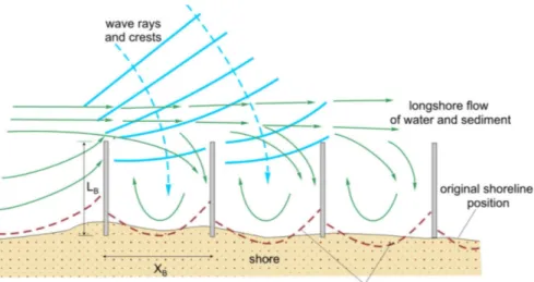
A groyne is a hard coastal defence structure perpendicular to the coast. They protect the coast by blocking (part of) the littoral drift and in this way trapping sand. This causes sedimentation seawards and erosion backwards of the structure. Groynes can be used individually, but most of the time they are combined in groyne fields (see Figure 2.1). Groynes can have special shapes and are either emerged, submerged or sloped. Regularly this solution is used in combination with beach nourishment.
Figure 2.1: Scheme of interaction of groynes, waves, currents and shore (Pruszak, n.d.).
Numerous investigations and observations have suggested that in order to create an optimal solution, the groynes should not go deeper seawards than 40-50% of the storm surf zone width (Neshaei and Biria, 2016). Apart from the length also permeability has an influence on their performance.
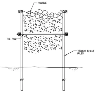
Different construction techniques and materials exist for the construction of groynes. It is possible to construct them out of timber (Figure 2.2), steel, concrete, rubble-mound, geobags or combinations thereof. A composite groyne is visualized in Figure 2.3., this structure consists of two sheet pile walls, commonly made out of timber, whereas the space in between is filled with gravel, sand, earth or stone. To avoid the finer materials to wash out, rubble or rock is usually placed as a top layer (Perdok, 2002).
Figure 2.3: Filled sheet pile groyne (Perdok, 2002).
2.2 Defence structures parallel to the shoreline
2.2.1 Seawalls
A seawall is a vertical structure, built in parallel to the coastline and separating land from water. Its main objective is to prevent erosion and damage caused by the action of the waves. Typically, a seawall is a massive structure as it needs to resist the full force of waves and storm surges. Different types exist as shown in Figure 2.4. These defences can be used as an emergency solution at exposed city fronts or at degraded beaches without recreational use. Seawalls are often used in places where space is scarce and most of the time a promenade is situated on top of the wall. Seawalls have the disadvantage that they reflect most of the wave energy, in this way erosion at the toe of the structure is intensified. As wave run-up and wave overtopping are the main processes that need to be considered, the main design parameter of a seawall is the crest elevation (Sadeghi et al., 2018).
A seawall fixes the position of the coastline but does not succeed to hold back the ongoing erosion in the coastal profile. It is quite common that the beach disappears in front of a seawall, therefore it will often be necessary to strengthen the foot of the seawall with a rubble revetment after some years (Mangor et al., 2017).
Figure 2.4: Types of seawalls ( Mangor et al., 2017).
2.2.2 Revetments
A revetment is built to protect the foot of a cliff, dunes, a scarp or a seawall against erosion by wave action and currents. A revetment is always sloped and quite often constructed as a permeable structure by using natural stones or concrete blocks with openings. This permeability helps to absorb more wave energy and minimises the effects of reflection and wave run-up. Natural stones may be used either by theirself or their stability can be improved by using for example asphalt or gabions (Figure 2.5). A revetment is quite similar to a seawall, although it does not protect against flooding and is often used in addition to other types of protections such as seawalls and dikes. The function of a dike is to protect the low coastal hinterlands behind it from being flooded (Mangor et al., 2017).
2.2.3 Breakwaters
Breakwaters are the most used type of structure to protect large ports and coastal zones. They are classified as longitudinal structures in this summary but can as well be constructed perpendicular to the coastline. Mound breakwaters are the most common and have a simple trapezoidal cross-section. They are used to minimize the intensity of wave action and they thereby provide harbourage or protect the shoreline (Figure 2.6). In case of port protection, the structure often has a crown wall so that the structure is not overtopped by waves. Mound breakwaters are composed of layers of stones: a core of smaller rocks covered by one or more filter layer(s). These layers are covered by a layer of armour units. These can either be natural quarry stones or special concrete units such as Cubipods (Medina and Gomez-Martin, 2016). In addition to mound breakwaters, vertical breakwaters are also commonly used. These structures consist of a foundation and a caisson. Advantages are the short execution time and the limited need of quarry material. Additionally, less space is occupied and it is possible to use the breakwater as a quay. A disadvantage however is the reflection of waves, to counter this antireflective measures sometimes need to be applied. Unfortunately the construction of the vertical caisson is only possible during specific climate conditions (small wave heights and mild currents) and therefore their application is not always possible.
Figure 2.6: Most common types of breakwaters (Ciria et al., 2007).
Less commonly used are floating breakwaters, these are mostly used to protect small harbors or marinas where wave lengths and heights are not too large. Floating breakwaters have a more modest impact on the wave attenuation, but their performance is almost independent on the variations of the water level (such as tides). Floating breakwaters are preferable where poor foundation possibilities prohibit the application of traditional breakwaters. For water depths greater than 6m traditional breakwaters are often more expensive than floating ones (Burcharth et al., 2015). The main problem with floating breakwaters is their low reliability in case of extreme waves as these induce large forces on the structure and mooring system.
2.2.4 Detached breakwaters
Detached breakwaters are more or less constructed parallel to the coast, inside or outside the zone where waves are depth limited (surf zone). They can be submerged or emerged but
accumulation can develop in either a salient or a tombolo as visualised in Figure 2.7. Detached breakwaters are widely used to prevent coastal erosion, to protect land from flooding or to increase the stability of beaches. They will likely be used in combination with beach nourishment.
Different forms of detached breakwaters exist such as low-crested breakwaters, floating breakwaters and submerged breakwaters. Floating breakwaters are not so commonly used nowadays due to their high costs and insufficient reliability in case of extreme wave heights (Burcharth et al., 2015). Low-crested and submerged breakwaters on the other hand are more common and their low visual impact is a big asset in touristic regions.
Figure 2.7: Illustration of tombolo and salient (Burcharth et al., 2007).
2.3 Low-crested and submerged structures
Up until now coastal defence structures were categorized by their orientation with respect to the shoreline. They can however also be divided by the level of wave overtopping as shown in Figure 2.8. Several defence structures have a high crest elevation so that there will be no overtopping or only a marginal overtopping under design conditions. Typically seawalls and port breakwaters are categorized as non-overtopped structures. LCS on the other hand are structures with their crest around the sea water level (SWL) and are characterized by significant overtopping. Submerged structures have their crest below SWL and are overtopped by all waves. The wave breaking process still affects their stability, whereas near-bed structures have a crest elevation low enough so that the hydrodynamics around the structure are not affected significantly by wave breaking (Ciria et al., 2007).
Figure 2.8: Coastal defence classification based on level of overtopping (Ciria et al., 2007).
Low-crested and submerged structures are further divided into different types based on their structural characteristics and purpose. A diagram of this classification is given in Figure 2.9. LCS are classified in three categories: traditional rubble-mound LCS, dynamically stable reef breakwaters and HLCS. Submerged structures are divided into broad-crested structures, geotextile sand containers (GSC), prefabricated concrete structures, artificial reefs and inflatable submerged structures. In chapter 3 more details will be provided regarding low-crested structures whereas chapter 4 focusses on submerged structures.
Figure 2.9: Low-crested and submerged structures classification. Low-crested structures (LCS) Rubble-mound LCS Reef breakwaters Homogeneous low-crested structures (HLCS) Submerged structures Broad-crested
structures containers (GSC)Geotextile sand Prefabricated structures Artificial reefs
Inflatable submerged
3 LOW-CRESTED STRUCTURES (LCS)
The term low-crested structure traditionally refers to rubble-mound coastal defence structures with a crest elevation near the still-water level. LCS have had promising results in attenuating erosion problems in touristic coastal zones and have had numerous applications in last decades. Three types of LCS will be analysed in this chapter: rubble-mound LCS (Figure 3.1), dynamically stable reef breakwaters (Figure 3.2) and the more innovative homogeneous LCS (Figure 3.3). The term reef breakwater refers to a homogeneous low-crested pile of stones without the classical multilayer cross-section. Their initial shape is allowed to be deformed by severe waves so that an equilibrium shape establishes. The other two types are statically stable hence not allowed to deform.
Figure 3.1: Rubble-mound LCS cross-section (van der Meer et al., 2005).
Figure 3.2: Dynamically stable reef breakwater cross-section (Ahrens, 1989).
In the following paragraphs more information about these structures will be given. First general properties and concepts of LCS will be discussed. Thereafter the three selected types will be discussed in greater detail. To start with the rubble-mound LCS will be discussed as this is the most common type of LCS and is widely used. Thereafter the reef breakwater proposed by Ahrens in the late 1980s is explained. Documentation about this type is rather scarce, however it is important to mention because of its ultimate design simplicity. For HLCS, in addition to a brief literature review, a physical model testing method is discussed.
3.1 Introduction
Mostly LCS are detached from the shoreline and aligned more or less parallel to it. They are submerged or emerged, and characterised by significant amounts of wave overtopping (Burcharth et al., 2015). Low-crested structures create a milder wave climate in the lee side of the structure by reflective and dissipative wave transformation processes. As a result of these processes, the waves reaching the coast are smaller and therefore the sediment carrying capacity is reduced, resulting in less coastal erosion. These types of structures can only be applied in situations where some agitation is acceptable as not all wave energy is dissipated.
LCSare not only valuable to mitigate coastal erosion but can also be used to protect existing
non-overtopped structures and/or to adapt them to more severe conditions such as sea level rise.
3.1.1 Advantages and disadvantages
The low visual impact, which is mainly important in touristic regions, is the most important reason why LCS are favoured in last decades. Additionally, overtopping of the structure favours good water circulation in the lee side. This results in a better water quality compared to non-overtopped structures. LCS appear to be similar to natural reefs, they attract fishes and are therefore popular among fisherman. In comparison to a breakwater without overtopping, the impact on the transport climate and on the sand accumulation is smoother (Mangor et al.,
2017). Besides this, LCS are more stable and are cheaper from an economical perspective
(d’Angremond et al., 1997).
Nevertheless, some disadvantages are associated with LCS as well. They provide only partial attenuation of the wave action and therefore the shore protection and coastal protection are also partial. On top of this the overtopping waves initiate local currents which could be hazardous for swimmers or smaller vessels (Mangor et al., 2017).
3.1.2 Wave interaction
When waves reach LCS, several physical processes occur. One part of the wave energy is reflected on the relatively steep slope while another part is dissipated by breaking on the crest of the structure (Gourlay, 1996) or/and by the flow through the structure. This porous flow through the structure is caused by the incident waves and energy is dissipated by air
overtopping. These principles are illustrated in Figure 3.4, where also the difference between an emerged and submerged structure is shown.
Figure 3.4: Energy transfer at submerged and emerged breakwater (Schoonees et al., 2019).
The incident energy is equal to the sum of the dissipated, reflected and transmitted energy. Theoretically the following formula is valid:
𝐸 = 𝐸 + 𝐸 + 𝐸 (3.1)
Attention should be paid as the reflected energy accumulates with the incident waves and gives rise to bigger wave heights on the seaward side of the structure. As a result of the presence of a LCS the transmitted energy (and hence the wave height behind the structure) is smaller than the incident. The degree of wave attenuation depends on the climate conditions and the geometry (Pilarczyk, 2003). Besides the described effects which cause the waves in the lee side to have a lower wave height and mean period, several 3D phenomena occur such as diffraction, refraction and generation of currents (Burcharth et al., 2007). Furthermore, broad-crested structures also dissipate energy from the ‘overflowing’ waves by friction with the crest of the structure.
3.1.3 Wave transmission and reflection
The wave transmission is defined by the transmission coefficient (Kt), which is the ratio of the
transmitted significant wave height (𝐻 ) to the incident significant wave height (𝐻 ). This represents the transmitted energy from open sea to the sheltered area between the breakwater and the coastline (Giantsi and Moutzouris, 2017).
𝐾 = 𝐻
𝐻 (3.2)
The reflection that appears in front of the breakwater is expressed as the ratio of the reflected significant wave height (𝐻 ) over the incident significant wave height.
𝐾 = 𝐻
𝐻 (3.3)
The dissipation that appears is often expressed by the dissipation coefficient (Kd). As wave
energy is proportional to the wave height squared and the sum of reflected, transmitted and dissipated energy is equal to the incident energy, the following equation can be composed:
𝐾 + 𝐾 + 𝐾 = 1 (3.4)
In Figure 3.5 an overview is given of the parameters with the most significant influence on wave transmission at LCS.
Figure 3.5: Parameters that affect wave transmission (DELOS, 2002).
The crest freeboard (Rc) is the distance from the breakwater crest to the MWL, note that
emergent breakwaters have positive values (Cappietti et al., 2012). For low-crested structures, the crest freeboard will be one of the most influencing parameters for wave transmission as it defines the amount of overtopping. The lower the freeboard, the higher the wave transmission.
Another geometric parameter is the crest width (Bc). It is clear that a wider crest leads to less
transmission as a wide crest will induce more wave breaking and consequently more energy is dissipated, resulting in a lower transmission coefficient (Daemen and Van der Meer, 1994). In case of structures with a positive freeboard the wave transmission will also be influenced by the angle (α) and the roughness of the seaward slope. On a gentler and rougher slope more energy will be dissipated and less transmission occurs. For submerged structures this influence becomes negligible (DELOS, 2002).
An important hydraulic parameter is the incident significant wave height. An increase in Hi will
result in a lower transmission coefficient as more energy will be dissipated by the breakwater. Smaller waves on the other hand will almost not be affected by the structure, this is especially the case for submerged structures. As waves are mostly depth limited, also the water depth
(h) has an influence on the transmission coefficient. The influence of the wave period (T ) can
𝑠 =2𝜋𝐻
𝑔𝑇 (3.5)
3.1.4 Design of LCS
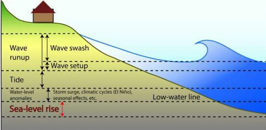
The design of a LCS can be divided in a preliminary design phase and a detailed design phase. In the preliminary design phase the feasibility of the proposed solution is examined and several alternative LCS-schemes are formulated. Afterwards the favoured schemes are studied in detail and optimised in order to increase structural reliability and cost-effectiveness. To select the best options among several alternative designs, several performance criteria have to be defined such as stability, hydrodynamic, morphological, ecological and economic criteria. Before providing solutions, the boundary conditions at the site need to be investigated, therefore the historic data regarding water levels, currents, wind, waves, bathymetry, … have to be collected. Attention should be paid to doing this carefully as water levels are very important in structural and functional design of LCS. Water levels determine both the maximum wave heights in shallow water and the freeboard of the structures. Together they basically control wave transmission (Burcharth et al., 2007) and thus the effectiveness of the LCS. Water level variations are caused by several phenomena as can be seen in Figure 3.6. These are on one hand caused by climate change induced sea level rise which is largely uncertain (but in the order of 3mm/year (Vitousek et al., 2017)). On the other hand, tidal variations caused by the position of celestial bodies (astronomical tide) or storm surges (meteorological tide) also cause water level variations. It is possible to predict the astronomical tide very precisely and to treat it as deterministic. Meteorological tides on the other hand, should be treated as a stochastical process. On top of this, wave setup and wave swash also cause changes in water level. For beaches with a natural slope wave setup and swash are significant, however for LCS which have a steep slope angle (α) this is not applicable.
During design attention should still be paid to the visibility of the construction as low visibility is one of the main advantages of LCS. If the low-crested structure would be designed for conditions of high tide and storm surge it would be rather high relative to the normal water-level (Mangor et al., 2017). For structural design reliability the high tide and storm surge water levels are indeed needed. However, for functional design and morphologic impacts, the more frequent water levels are representative. Regarding wave characteristics, the joint statistics of tides and waves should be considered as their combined effect determines the structural and morphological impact. The most important wave characteristics which should be obtained are
the significant wave height Hs (which is later on used in structural formulae) and the root mean
square wave height Hrms (which is mostly used for numerical modelling of morphodynamics)
(Burcharth et al., 2007). For both of these, the corresponding wave period should also be obtained, as well as the main wave direction.
A known issue for LCS is the possible settlement which reduces the degree of coastal protection in a similar way as a sea-level rise would do. This should also be taken into account for the design.
This being said, it is clear that designing a LCS has many aspects. For each type of structure the structural design will be discussed more profoundly as well as the transmission and reflection characteristics associated with the geometric design.
3.1.5 Scour protection
As submerged and low-crested structures generally induce wave breaking, new currents develop. If the structures are not properly designed, these currents can lead to circulation patterns which enhance shoreline erosion. In case of detached breakwater series, the currents are driven by differential breaking of waves over the structure (Villani et al., 2012). Also currents around the breakwater, which induce scour, may occur and therefore a careful design is needed. Traditionally a protection apron is used to protect against scour. This should be designed so that it can withstand the wave and current forces, moreover it should be flexible
enough to adapt to possible scour. The width of the protection apron (Wa) should be sufficiently
large to provide adequate protection for the stability of the breakwater. The same width may be selected for the toe protection apron at the lee side and seaward side.
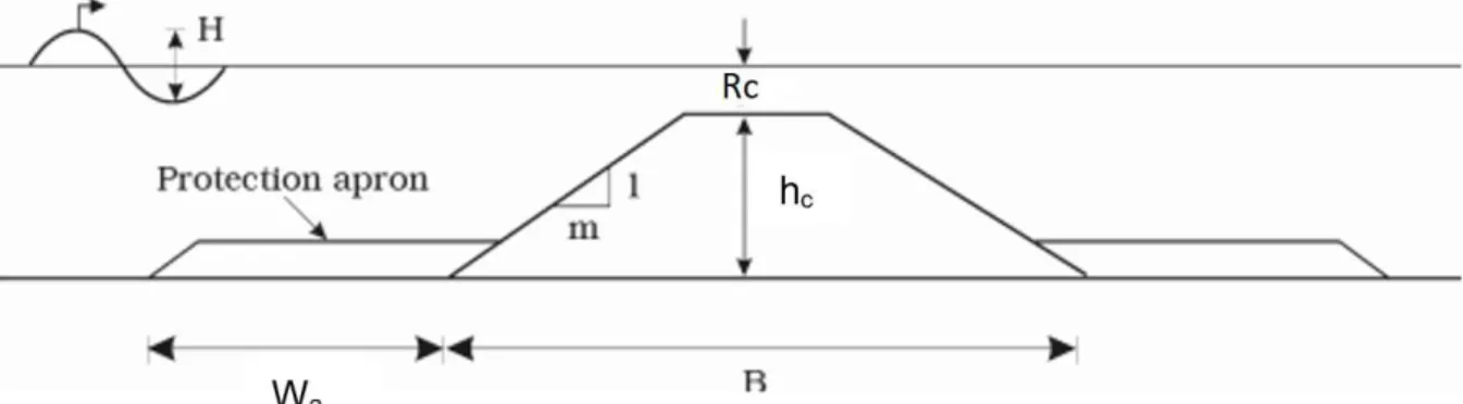
In DELOS (2002) the following empirical equation is presented to calculate the length of the protection apron (Wa):
𝑊 = 1 −𝑚 ℎ𝐿
4 𝐿
4 (3.6)
Where m is the slope of the surface of the breakwater (m=cot(α)), hc is the height of the
Figure 3.7: Scour protection apron and influencing parameters according to DELOS (2002).
A scour protection typically consists of loose stones also known as riprap. The stability of riprap may be increased by penetrating the pores with a grout. Another option is to use mattresses, such as gabion mattresses. Commonly geotextile filters are used in combination with a permeable scour protection in order to prevent erosion of the soil particles underneath (De Mulder, 2019).
3.1.6 Shoreline response to detached LCS
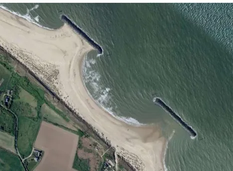
As a detached breakwater changes the existing currents and diminishes wave heights on the lee side, it affects the sediment course and the areas of erosion and deposition. A detached breakwater can modify the littoral transport in a smoother way compared to a groyne (paragraph 2.1.1). Deposition patterns are often referred to as salients or tombolos (see Figure 3.8). Tombolos will interrupt littoral currents, causing a similar shoreline response as groynes: accretion upstream and erosion backward (Burcharth et al., 2015). Salients are less damaging from this point of view, as their interference with longshore sediment transport is smaller. In Figure 3.9 an aerial view of a coastal site is shown where tombolos are formed.
Figure 3.9: Aerial view of detached breakwaters at Sea Palling, Norfolk, UK (image from Google Maps).
The influence of the design with respect to beach morphology is analysed by considering the long term effects as morphological changes progress slowly. Morphological response to a LCS is influenced by multiple variables and the most important ones are the distance between coastline and structure, length of the structure, transmissivity of the LCS, beach slope, mean wave height and period, orientation angle of the LCS and the predominant wave direction. For series of detached breakwaters, the gap between segments is also a primary variable (Pilarczyk, 2003). The variables influenced by the LCS design are thus its location, its length and the transmission characteristics.
The response of the coastline is largely dependent on the ratio of the breakwater length (LB)
to the distance to the shoreline (X) (Mangor et al., 2017). When this ratio is smaller than approximately 0.6 to 0.7, a bell shaped salient will be formed at the lee side of the breakwater. On the other hand, when this ratio is greater than 0.9 to 1.0 it is expected that a tombolo will be formed. This is however an estimation, the determination of the shape of the coastline is dependent on many other parameters as well. Therefore it is common practice to use numerical modelling to determine the morphological change. Most numerical models incorporate the relevant processes such as wave transformation, refraction, diffraction, wave breaking and the resulting current generation and sediment transport. But in general the following rule of thumb is valid:
𝑆𝑎𝑙𝑖𝑒𝑛𝑡 𝑓𝑜𝑟 𝐿
𝑋 < 0.6 𝑡𝑜 0.7 (3.7)
𝑇𝑜𝑚𝑏𝑜𝑙𝑜 𝑓𝑜𝑟 𝐿
3.1.7 Environmental aspects
In recent years there has been an increased attention for the environmental impact of coastal defences, so in this paragraph the environmental impact and some mitigation measures for LCS will be discussed.
3.1.7.1 Environmental impact of LCS
Coastal areas have diverse ecosystems with great value. In recent decades these areas have been protected by hard coastal defence structures such as LCS. These structures affect the landscape and the functioning of coastal ecosystems. Impacts can occur locally near the structure (10-1000m) but can also scale up to surrounding areas and ultimately affect coastal ecosystems on a regional scale (100 -1000km) (Airoldi et al., 2005). Very often it is indispensable to find harmony between the solutions preferred by engineers and ecologists (Zanuttigh et al., 2005).
Results of the DELOS project give certain general impacts of hard structures. Locally, there is a loss of soft-bottom habitat since it is covered by the structure. Secondly, the lower wave height at the lee side of the structure influences the characteristics of soft-bottom sediments. As a consequence there are changes in the biodiversity on the sandy bottom. Similarly, the higher wave energy in front of the structure will affect the sediment transport on that side and scour may occur. Another impact of LCS is the introduction of an artificial hard-bottom habitat that is colonised by animals and plants found in nearby rocky shores, coastal lagoons or other artificial structures. This can lead to the development of new species or increased abundance in species present in small numbers on other artificial substrates. All these consequences together (the changes in species composition, abundance and diversity) can change the functioning of coastal ecosystems. On a regional scale, hard coastal defence structures can serve as stepping stones for species (see Airoldi et al., (2005) for more information). Airoldi summarised the most important design parameters affecting the biologic impact of LCS (Table 3.1).
Table 3.1: Summary of critical design features affecting the effects of LCS and other hard defence structures on coastal environments and associated biota (Airoldi et al., 2005)
The main environmental impact of LCS will happen during the construction phase. Heavy machinery and the used materials will have a direct impact on the sediment structure and the associated biodiversity. Rubble-mound construction implies suspended materials and the accumulation of fine sediments on the seabed which threatens the fringe communities and