Concrete core activation
Kennisbank Bouwfysica
Author: dr. ir. Peter van den Engel, dr. Regina Bokel and ir. Leo de Ruijsscher
1 Introduction
With concrete core activation water pipes for heating and cooling are integrated in the concrete floor or in a wall. Other names for concrete core activation are slab heating and cooling or thermo active building systems (TABS). Concrete core activation can be combined with high temperature cooling (for instance 18oC) and low temperature heating (for instance 24oC). The system can easily be connected to a heat pump and to a system that extract energy from the natural surroundings (air, sky, water, ground or a buffer, such as an aquifer). Due to the fact that the water temperatures in the floor usually only slightly differ from the average room temperature, a high exergetic efficiency is possible. A typical heating and cooling power of concrete core activation is 50 W/m2 at an average temperature difference of 3oC between the room and the surface temperature. Concrete core activation makes use of the energy of the water flow through the floor and of the cooled or heated thermal mass of the floor as well. Ca 60% of the heat transport is radiation and 40% convection. Because of the high radiation part of the energy flow, the velocities in a room heated or cooled with concrete core activation are generally low. However, the system reacts very slowly on a change in temperature of the water, so it is not an appropriate system for individual climate control. In most cases the system is combined with a ventilation system that only supplies the minimum amount of air that is necessary for air quality 25 – 50 m3/h per person, CO2-level < 1.200 ppm).
2 Calculation methods
There are several methods to check whether the concrete core activation is able to cool or heat in W/m2 within the expected range. In several steps the capacity and thermal
characteristic of the floor can be evaluated:
1. General approach of the cooling and heating capacity: The expected surface temperatures, combined with the heat transfer coefficients can predict the thermal flow.
2. Calculation of the thermal capacity of the water flow. This should match with the expected thermal flow from the surface.
3. Calculation of the thermal flow and surface temperatures via a thermal resistance model, following NEN-EN 15377-1. The effect of floor covering or acoustical measures at the ceiling can be evaluated.
4. Calculation of the storage capacity and thermal response of the floor. These are important parameters for the cooling capacity, thermal comfort and efficiency of electricity supply (cooling during the night).
2.1 General approach of the cooling and heating capacity: The expected surface
temperatures, combined with the heat transfer coefficients can predict the thermal flow.
In order to know how much heating or cooling energy can be supplied the following equation can be used:
;
c sp
α θ
iΦ
=
∆
(W/m2) (1)where:
Φc;sp = specific cooling flow in W/m 2
Δθ = temperature difference between the air and the surface in K αι = heat transfer coefficient (radiation and convection) in W/m2K
When the surface and room temperature are known, it is possible to calculate the thermal flow to the room, making use of the heat transfer coefficient. In the NEN-EN 15377-1 the following values of the transfer coefficients (α) are given (table 1 and figure 1):
Table 1: Heat transfer coefficients according to NEN-EN 15377
Floor heating and ceiling cooling Φc;sp = α Δθ = 8.92 Δθ 1.1 W/m2
Floor cooling Φc;sp = α Δθ = 7.00 Δθ W/m2
Ceiling heating Φc;sp = α Δθ = 6.00 Δθ W/m2
Wall heating and wall cooling Φc;sp = α Δθ = 8.00 Δθ W/m2
The difference between the heat transfer coefficients can be explained as follows: Cold air flows down en hot air rises, so a cooled ceiling and a heated floor have higher heat transfer coefficients, because they support the natural convective flow. The radiation part of the thermal flow does not depend on the position of the hot or cold part.
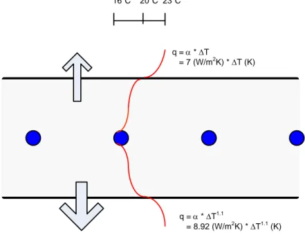
q = α * ∆T
= 7 (W/m2K) * ∆T (K)
q = α * ∆T1.1
= 8.92 (W/m2K) * ∆T1.1 (K) 16oC 20oC 23oC
Figure 1: Example of concrete core activation with a cooled floor, and an estimated temperature profile (the chosen symbols are a little different, but common as well).
With a surface temperature of a cooled floor of 20oC and an air temperature of 23oC the upward cooling flow is 7 W/m2K * 3 K = 21 W/m2 and the downward 8.92 W/m2K * 31.1 K = 29.9 W/m2. The total cooling flow will be 50.9 W/m2. Depending on the insulating effect of the floor covering, the upward cooling flow is often half this value.
Figure 3 shows a heavy weight construction with pipes integrated in the floor. Another option is a light weight construction with pipes embedded in a metal panel, just below the floor or wall covering; see figure 4.
insulation floor of wall covering
construction material
Figure 2: Light weight construction with pipes in a metal panel.
The floor temperature will be slightly lower (ca. 0,5oC compared to the former example) when the resistance of the floor covering is the same, and the thermal response is higher than concrete core activation.
The effect on thermal comfort
The temperatures of the floor and the ceiling are limited by thermal comfort requirements. These requirements are mentioned in the ISO 7730. For a heated ceiling the radiation
asymmetry for a sitting person should be less than 5 K related to a maximum of 5% predicted percentage of dissatisfied people. Taking into account a certain angle factor (af)1 for a room with equal wall temperatures, the maximum ceiling temperature can be calculated:
(
af
θ
ceiling+ −
(1
af
)
θ
room)
−
θ
room<
5
K
(2)5
room(1
)
room ceilingK
af
af
θ
θ
θ
<
+
− −
(3)For an angle factor of 0.27 (length room 12 m, width room 6 m, room height 2.6 m) and a average wall and room temperature of 20oC the maximum ceiling temperature could be 38oC. However, the top of the walls will be heated up as well, which will increase the angle factor. As a rule of thumb maximum ceiling temperatures of 32oC are recommended. With a maximum angle factor of 0.46 - for a very large space - the maximum temperature will be 31oC.
2.2 The thermal capacity of the water flow
In order assess the cooling capacity of the water flow at a fixed temperature difference the following equation can be used:
c
q
vρ
c
θ
Φ =
∆
(W) (4)where:
Φc = cooling flow W
qv = volume flow m3/s
ρ = volume mass of water ≈ 1.000 kg/m3 c = specific heat of water ≈ 4.200 J/(kg.K) Δθ = temperature difference between supply and runoff K
A cold supply of 30 W/m2 for a floor area of 10 m2 (Φc = 300 W) and a temperature difference of 1 K between supply and runoff water will lead (with equation 2) to the following water volume flow: c v
q
c
ρ
θ
Φ
=
∆
=300
1.200 4.200 1
W
= (5)0,000071 m3/s = 0,071 l/s = 255 l/h. For an area of 10 m2 is this = 25.5 l/hm2. In a floor with pipes which have an internal diameter of 15 mm the velocity will be:
v
q
u
A
=
(m/s) (6) u = velocity m/s 1A = surface of the pipe (= 2
2
r
π
) m2 u = 0.000071 / ((π . 0.015/2)2 ) = 0,40 m/s.This velocity is low. The velocity will become higher with: - a pipe with a smaller diameter
- a longer pipe and the same cooling capacity per m2 (a larger floor field) - larger cooling capacity per m2 and the same ∆T of 1 K
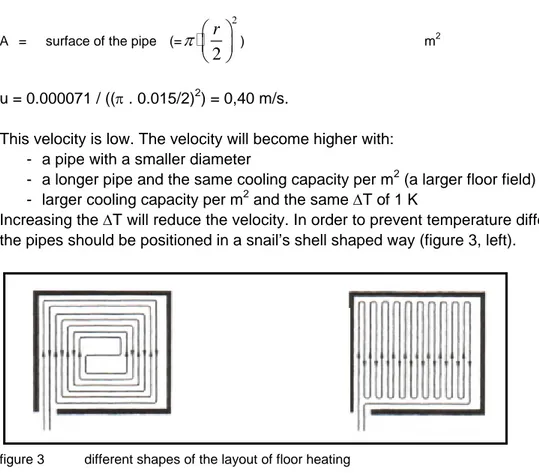
Increasing the ∆T will reduce the velocity. In order to prevent temperature differences in a floor the pipes should be positioned in a snail’s shell shaped way (figure 3, left).
figure 3 different shapes of the layout of floor heating
Pump energy
The pump energy is related tot the velocity of the water: 2
0, 5
P
=
ρ
u
(7)P = pressure Pa
ρ = volumetric mass of water kg/m3
u = water velocity m/s
In order to reduce pump energy, the velocity should remain below 1 m/s. For example, 1 m/s will result in a pressure difference of at least 250 Pa, only related tot the velocity (equation 7). However, the resistance of the pipe is a very important factor. 1 m/s in a plastic pipe with an internal diameter of 16 mm will result in a total resistance of 900 Pa/m. A velocity of 0.5 m/s results in 290 Pa/m. A velocity of 0.5 m/s in a pipe of 6.4 mm will result in a pressure
difference of 600 Pa, which shows that lower velocities are required in smaller tubes in order tot prevent high pressure differences. In dwellings the maximum pressure difference of the heating system is normally 40.000 Pa. For floor heating in a house 20.000 Pa is advised to be the maximum. The total length of a pipe-segment in a house (see figure 3) should not exceed ca 70 to 100 m. In offices length of pipes of 240 m are also possible.
2.3 The heat flow and surface temperatures by calculation
In order to understand the influence of the several different layers on the capacity of concrete core activation it is necessary to model the floor as a network of resistances. This method is used in the NEN-EN 15377-1 as well.
The heat flow is calculated with the following equation:
;
c sp
U
θ
Φ
=
∆
(W/m2) (8)where:
Φc;sp = specific cooling flow in W/m 2
Δθ = temperature difference between the air and the surface in K U = heat transfer coefficient W/m2
K
U1 = 1/R1. R1 is the thermal resistance of the upper layer above the centre of the pipes and U2 = 1/R2 R2 is the thermal resistance of the lower layer below the centre of the pipes. The temperature difference Δθ is the difference between the water temperature in the pipes and the air temperature in the room. The method in the NEN-EN 15377-1 is much more detailed. In this case a simplified method is used:
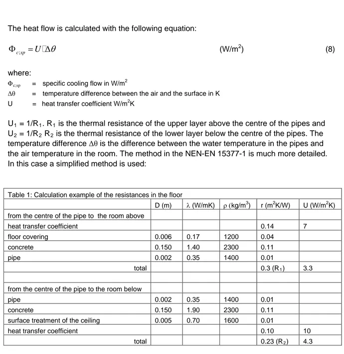
Table 1: Calculation example of the resistances in the floor
D (m) λ (W/mK) ρ (kg/m3) r (m2K/W) U (W/m2K) from the centre of the pipe to the room above
heat transfer coefficient 0.14 7
floor covering 0.006 0.17 1200 0.04
concrete 0.150 1.40 2300 0.11
pipe 0.002 0.35 1400 0.01
total 0.3 (R1) 3.3
from the centre of the pipe to the room below
pipe 0.002 0.35 1400 0.01
concrete 0.150 1.90 2300 0.11
surface treatment of the ceiling 0.005 0.70 1600 0.01
heat transfer coefficient 0.10 10
total 0.23 (R2) 4.3
Following the calculation results from table 1 a temperature difference of 7 K between the pipe and the room temperature will result in a temperature flow to the top of 7 * 3.3 = 23.1 W/m2 and a flow of 10 * 4.3 = 43 W/m2 to the underside of the floor. This is ca 66 W/m2 in total. A water temperature of 16oC and a room air temperature of 23oC will result in a surface temperature of ca 20oC. This surface temperature is high enough to prevent condensation when natural ventilation makes part of the climate system. More common is a water
temperature of 18oC and room temperature of 25oC. In that case the surface temperature will become 22oC.2
2
In this case the spacing between the pipes is neglected, so in reality the temperature differences are slightly higher.
2.3 The storage capacity of the floor and the thermal response
Concrete can store much heat or cold. For instance, concrete can be cooled or heated during the night when there are no occupants and peak cooling loads can be reduced.
. .
Q
=
ρ
c T
∆
(9)Q = energy storage capacity of the floor J/m3 ρ = volumetric mass of the floor kg/m3 c = specific heat of the floor J/kgK ∆T = temperature difference K
When a floor of 0.20 m concrete (ρ = 2.000 kg/m3
, c = 840 J/kgK) increases or decreases 1 K in temperature, the stored extra energy is 336.000 J, according tot equation 9. This is the same as an energy flux of 17 W/m2 during 5.4 hours. However, in reality there is a delay in heat and cold supply because of the inertia of the thermal mass, so the energy flux will reduce slowly and the period of heat or cold supply will take more time. This can be reduced by increasing the temperature difference between the water and the air and by the location of the pipes.
3. Examples
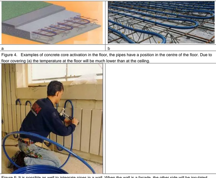
a b
Figure 4. Examples of concrete core activation in the floor, the pipes have a position in the centre of the floor. Due to floor covering (a) the temperature at the floor will be much lower than at the ceiling.
Figure 5: It is possible as well to integrate pipes in a wall. When the wall is a façade, the other side will be insulated and most of the thermal energy will flow to the room.
4. Suspended ceilings
A suspended ceiling is not necessary or advisable, due to the fact that heat/cold transport from the ceiling is prevented. Suspended ceilings reduce the thermal capacity of concrete core activation due to the reduction of radiation, which is often half of the heat flow. However, a suspended ceiling might be an option especially when there is enough air flow above the ceiling or when the surface of this ceiling is less than 50% of the floor area. The temperature difference with the surrounding air has to be increased in order to obtain the same capacity. Without a ceiling, the height of the room can be increased. Without a suspended ceiling
acoustical problems can occur, such as a long reverberation time and bad speech intelligibility. These problems can be solved as well by baffles, better acoustical properties of the walls or floors. A rule of thumb is that ca 25 % of all the surrounding walls should have a high acoustical quality (90% noise absorption).
5. Literature
1. NNI. NEN-EN 15377-1. Heating systems in buildings – Design of embedded water based surface heating and cooling systems – Part 1: Determination of the design heating and cooling capacity. July 2008.
2. NNI. NEN-EN 15377-2. Heating systems in buildings – Design of embedded water based surface heating and cooling systems – Part 2: Design, dimensioning and installation. July 2008.
3. NNI. NEN-EN 15377-2. Heating systems in buildings – Design of embedded water based surface heating and cooling systems – Part 3: Optimizing for use of renewable energy sources. July 2008.
4. NNI. ISO 7730. Ergonomics of the thermal environment. Analytical determination and interpretation of thermal comfort using calculation of the PMV and PPD indices and local thermal comfort criteria. 2005.
5. NNI. ISO 7726. Ergonomics of the thermal environment. Instruments for measuring physical quantities. 1998.
6. ISSO-SBR-TVL symposium. Afgiftesystemen en comfort bij duurzame energietechnieken. 9 november 2006.
7. ISSO. Publikatie 18. Leidingnetberekeningen. 1987
8. ISSO. GIW-ISSO-publikatie 2008. Installatie-eisen 2008. Ontwerp en montageadviezen nieuwbouw eengezinswoningen en appartementen. Augustus 2008.
9. TU-Delft. Verhoeven AC. Gc 45. Bouwfysica. 1982.