Building Acoustics
7
Flanking Sound Transmission
by J.J.M. Cauberg, A. Schuur and M.J. Tenpierik
7.1
Introduction
One of the most important assignments of architectural acoustics is to control the sound transmission between two rooms. In the chapter on “Health” the Dutch “Bouwbesluit” puts requirements on the characteristic air-borne sound insulation index, Ilu;k, between an enclosed room in a dwelling and an
enclosed room or a set of enclosed rooms in an adjacent dwelling. From a quality perspective it is quite common to even use more stringent requirements (3 to 5 dB) than specified herein. This characteristic air-borne sound insulation index, Ilu;k, is defined in Dutch standard NEN 5077 “Geluidwering in
woongebouwen-Bepalingsmethoden voor de grootheden voor luchtgeluidisolatie, contactgeluidisolatie, geluidwering van uitwendige scheidingsconstructies en geluidniveaus veroorzaakt door installatie”. It uses the normalised air-borne sound reduction index, DnT, as a basis. Since DnT is a measure of the sound
pressure level difference between two rooms (Lp;r – Lp;s), it includes via Lp;r all sound transmission between
two rooms, i.e. direct and flanking transmissions. To check a situation against building codes thus requires knowledge of flanking transmission.
To characterise the sound transmission between two rooms often only the direct transmission through the partition wall is considered:
(
)
; ; 10log /
p r p s d d r
L =L −R + S A (7.1),
with
Lp;r = sound pressure level inside receiver room [dB] Lp;s = sound pressure level inside sender room [dB] Rd = air-borne sound insulation of partition wall [dB] Sd = surface area of partition wall [m2]
Ar = total sound absorption of receiver room [m2 sabin]
Although not further specified in the “Bouwbesluit”, the influence of flanking walls on sound transmission is limitedly mentioned: “in practise, the predicted sound pressure level in the receiver room (according to equation 7.1) is approximately 1 to 2 dB higher because of flanking transmission and sound leaks provided the construction is well-constructed”. NPR 5070 “Geluidwering in woongebouwen. Voorbeelden van wand- en vloerconstructies” (1993; “sound insulation in buildings. Examples of wall and floor constructions”) more specifically puts requirements on flanking walls specifically related to their mass.
In this chapter, flanking sound transmission between two rooms via the building construction (flanking walls) will be treated.
7.2
Flanking Sound Transmission: Air-Borne Excitation
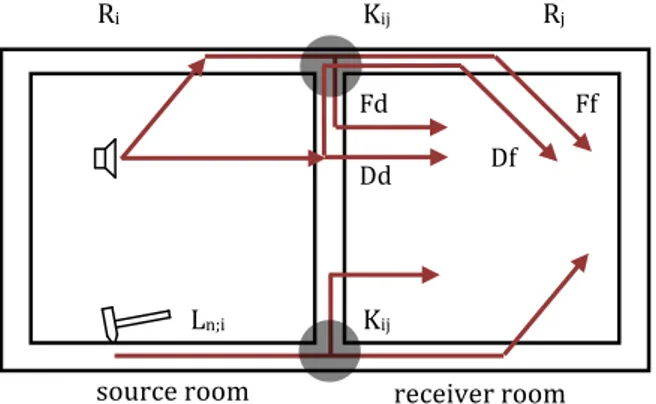
7.2.1 Acoustic modelThe possible sound transmission paths between two rooms are depicted in Figure 7.1. For the direct path (Dd) equation (7.1) is valid. It is explained in previous chapters. Sound transmission via the flanking paths Ff, Df and Fd will be treated in detail in this chapter using an acoustic model. For computing the sound pressure level in the receiver room, caused by sound energy transmitted from sending to receiver room via a flanking path, a mathematical relationship like equation (7.1) will be derived which allows for the calculation of DnT and Ilu;k using an easy computation scheme.
Figure 7.1 – Transmission paths of sound from one room to another.
Concerning the sound pressure level in the receiver room, Lp;j, resulting from a sound power radiating from
surface j, Lw;j, the following applies:
= +10log 4
pj wj
r
L L
A (7.2a).
As a result, the following also applies:
ρ = 2 ; 4 j eff j air air r W p c A (7.2b), with
Lp;j = sound pressure level inside receiver room resulting from surface j [dB] peff;j = sound pressure inside receiver room resulting from sound power Wj [N/m2] Lw;j = radiated sound power level by surface j [dB]
Wj = radiated sound power by surface j [W]
ρair = density of air [kg/m3] cair = speed of sound in air [m/s].
The sound power which radiates from a vibrating surface j can be calculated as:
2 j j air air j j
W =ρ c v S σ (7.3),
with
Sj = surface area of surface j [m2]
σj = radiation factor of surface j [-].
vj = the averaged vibration velocity of surface j [m/s]
As p2eff is a measure of the amplitude of the sound in air, v2j defines the amplitude of the vibration in a
vibrating construction. The radiation factor is a measure for the amount of acoustic energy that can radiate from a vibrating surface. This factor depends on frequency: above the coincidence frequency of the surface it is 1; below this frequency it is smaller than 1; and at this frequency it is larger than 1. The radiation factor is not only influenced by coincidence frequency but also by the dimensions of the wall. Because a wave in surface i having a vibration velocity, vi (Figure 7.1) travels via the junction to surface j,
surface j starts to vibrate with a certain velocity, vj. However, at this junction between surface i, j and the
partition wall dampening of the amplitude of the bending wave occurs. As a result
2 2
j ij i
v
=d v
(7.4).source room receiver room Ln;i Kij
Dd Fd
Df Ff
The vibration velocity of surface i, 2 i
v , is determined by the (direct) sound insulation of surface i. The following applies:
τ
= ; ; i radiated i i incidentW
W
(7.5), 2 ; ii radiated air air i i
W
=ρ
c v S
σ
(7.6),ρ
= 2 ; ; 4eff s i i incident air airp S
W
c
(7.7), in whichτi = sound transmission coefficient of surface i (Ri = 10 log 1/τi) Wi;radiated = the radiated sound power of surface i [W]
(assuming that surface i were a direct partition wall between two rooms) Wi;incident = the incident sound power on surface i resulting from a diffuse sound
field in the sending room [W]
peff;s = the effective sound pressure in the sending room [Pa].
Combining equations (7.5), (7.6) and (7.7) gives:
2 ; 2 2 2. 4 eff s i i air air i
p
v
c
τ
ρ
σ
= (7.8)The flanking sound transmission coefficient, τij, via the surfaces i and j can now be defined as the ratio of
the sound power which radiates from surface j in the receiver room and a reference sound power. Since the total sound transmission from the sending towards the receiver room is the sum of all sound transmissions via all surfaces, it is advantageous to use just one reference sound power in the sending room. We have seen in previous chapters that for determining the air-borne sound insulation of wall constructions, the incident sound power on the partition wall between two adjacent rooms, Wd;incident, is taken. This sound
power equals
ρ
= = 2 ; ; , 4 eff s s ref d incident d air airp
W
W
S
c
(7.9), withWs;ref = the reference sound power in the sending room [W]
Wd;incident = the sound power hitting the direct partition wall in the sending [W]
Sd = the surface area of the direct partition wall [m2].
If no direct partition wall is available, Sd is assumed to be 10 m2.
Using equations (7.3), (7.4), (7.8) and (7.9) we can now write for the transmission coefficient τij
σ
τ
τ
σ
= = ; . j j j ij ij i d incident d iW
d
S
W
S
(7.10).One problem however arises here. In practice, the radiation factors σi and σj are often not known with
sufficient accuracy. A solution to this problem comes from using the principle of force reciprocity. This principle implies that the flanking sound transmission coefficient should remain the same if surfaces i and j are exchanged. Mathematically this implies that
Applying this principle to equation (7.10) results in σ σ τ τ σ = σ . j j i i ij i ji j d i d j S S d d S S (7.12a), and thus in
σ
τ
σ
τ
= 2 . . j j ji i i i ij jd S
d S
(7.12b).Combining equations (7.10) and (7.12) yields
τ
=
τ τ
i 2jij i j ij ji d
S S
d d
S
(7.13).If we finally take the logarithm of both sides and multiply with 10, we can write
= + + +10log 2 2 2 j i ij d ij i j R R S R D S S (7.14), with ij
D =
(
Dv ij; +Dv ji;)
/2 = the (directional) average junction dampening or velocity level difference [dB]Dv;ij = - 10 log dij = junction dampening [dB] Ri = air-borne sound insulation of surface i [dB] Rj = air-borne sound insulation of surface j [dB]
Ri and Rj are the air-borne sound insulation of these surfaces in the real situation (situ), thus including
dampening caused by the edge of the surfaces. As a reasonable approach the measured values from a laboratory (lab) can be taken for Ri and Rj. So,
;
; ; ;
;
10log s situ
i situ i lab i lab s lab T R R R T = − ≈ (7.15), in which
Ts = the structural reverberation time of the surface [s]
As the sound pressure level difference between sender and receiver room can be calculated according to equation (7.1) using the situation-independent parameter Rd and the situation-dependent parameters Sd
and Ar, the vibration level differences between surface i and j can also be determined from
context-independent and context-dependent parameters. This is done as follows
= −10log ij ij ij i j l D K a a (7.16), with
Kij = the normalised situation-independent vibration reduction index [dB] lij = the length of the contact line between surface i and j [m]
These geometric correction factors, ai and aj, are defined as π = 2 ; 2.2 i ref i air s i S f a c T f (7.17), with f = frequency [Hz]
fref = reference frequency (=1000 Hz).
As a reasonable global estimation, we can say that the value of a practical equals the value of S (a ≈ S number-wise), as a consequence of which equation (7.16) changes to
= −10log ij ij ij i j l D K S S (7.18).
Kij characterises the vibration transmission from surface i to j in a normalised way and independent of the
situation. Or in other words, using Kij allows a calculation of the actual junction dampening Dijif the
parameters lij, Sj and Si of the actual situation are known.
Equation (7.14) can now finally be re-written to the fundamental equation for calculating flanking sound transmission + = + ∆ + ∆ + +10log 2 i j ij d ij i j i j R R S R R R D S S + = + ∆ + ∆ + −10log +10log 2 i j ij d i j ij i j i j R R R R K l S a a S S + ≈ + −10log +10log 2 i j ij d ij i j i j R R K l S S S S S 10log 2 i j d ij ij ij R R S R K l + ≈ + + (7.19).
In this equation ∆Ri and ∆Rj reflect additional sound reduction resulting from floating screeds, suspended
ceilings or a lightweight wall in front of a massive wall. In case of lightweight ceilings, front walls or screeds in front of massive basic constructions, the additional sound insulation of these elements in a direction perpendicular to this element may be taken. In case of lightweight ceilings, screeds and front walls in front of lightweight basic constructions approximately half of their additional sound insulation in perpendicular direction may be taken (Bron-van der Jagt et al., 2010). If no such elements exist, these two terms can be neglected.
7.2.2 Junction dampening and the vibration reduction index
The dampening of acoustic waves inside building constructions occurring at their interface has primarily been experimentally determined. The currently available data mostly only concerns the parameter Dij as
expressed in equation (7.14). Concerning the situation-independent vibration reduction index, Kij, hardly
any directly measured data is available. The available data mostly derives from measurements of Dij
corrected with a global average value derived from practice as 5
ij ij
As can be derived from Figure 7.1, junctions can have the following configurations: - +-shape:
• with a straight transmission path • with a transmission path at right angles • with rigid connections
• with flexible connections
• with a lightweight double construction - T-shape:
• with a straight transmission path • with a transmission path at right angles • with rigid connections
• with flexible connections
• with a lightweight double construction • with a lightweight façade system - corner
- a change in construction thickness or materialization
A good overview of the vibration reduction index, Kij, with practical examples can be found in Gerretsen
(2001). These examples are depicted here as Figure 7.2 to 7.8. In these figures, Kij is expressed as function
of the ratio of masses of the construction elements coming together in the node. These Kij-values can only
be used in case the construction elements continue from one side of the node to the other and their masses remain the same. In the European standard EN 12354-1 Kij is expressed as function of M defined as
M = log (m┴ i / mi) (7.21a),
with
mi = the mass (per square meter) of construction i as part of transmission from i to j [kg/m3] m┴ i = the mass (per square meter) of the construction perpendicular to construction i [kg/m3]
In agreement with this standard, the variable M in the equations below the following figures is as
M = log (m2 / m1) (7.21b),
with
m1 = the mass (per square meter) of the flanking construction in the sending room [kg/m3] m2 = the mass (per square meter) of the partition wall perpendicular to construction 1 [kg/m3]
The choice for the mass ratio m2 / m1 is somewhat arbitrary for flanking transmission ‘around the corner’
since the vibration reduction index, Kij, for, e.g., the transmission from surface 2 to surface 3 is identical to
the one for transmission from surface 1 to surface 2. In case of flanking transmission ‘around the corner’ M could have been defined as log (m1 / m2) instead, producing the same result.
From Figures 7.2 to 7.8 we can derive that, if the partition wall with mass m2 is very heavy relative to the
flanking wall with mass m1, thus if m2 >> m1, the vibration reduction index Kij will be high. The values of Ri
and Rj of a lightweight flanking wall as used in equation (7.19) however will be small. The resulting
flanking sound reduction index of transmission path Ff via the lightweight flanking wall, RFf, will in that
case also be relatively small particularly at the higher frequencies.
As a final remark, the vibration reduction index, Kij, in many cases does not depend on frequency
(expressed with 0 dB/octave); in some other cases a frequency-dependency does exist. Such a dependency is then formulated below the figure.
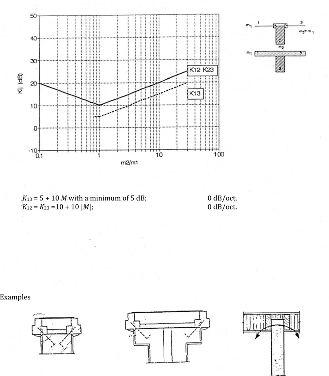
Figure 7.2 – Vibration reduction index of lightweight facade systems.
Examples
K13 = 5 + 10 M with a minimum of 5 dB; 0 dB/oct.
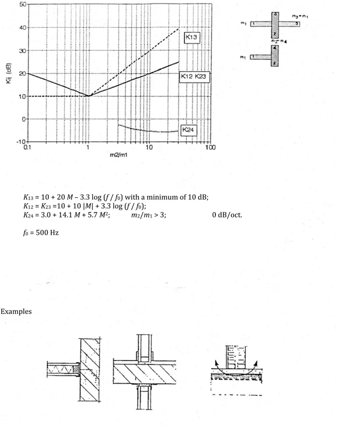
Figure 7.3 - Vibration reduction index of lightweight double consruction with a homogeneous construction.
Examples
K13 = 10 + 20 M – 3.3 log (f / f0) with a minimum of 10 dB; K12 = K23 =10 + 10 |M| + 3.3 log (f / f0);
K24 = 3.0 + 14.1 M + 5.7 M2; m2/m1 > 3; 0 dB/oct. f0 = 500 Hz
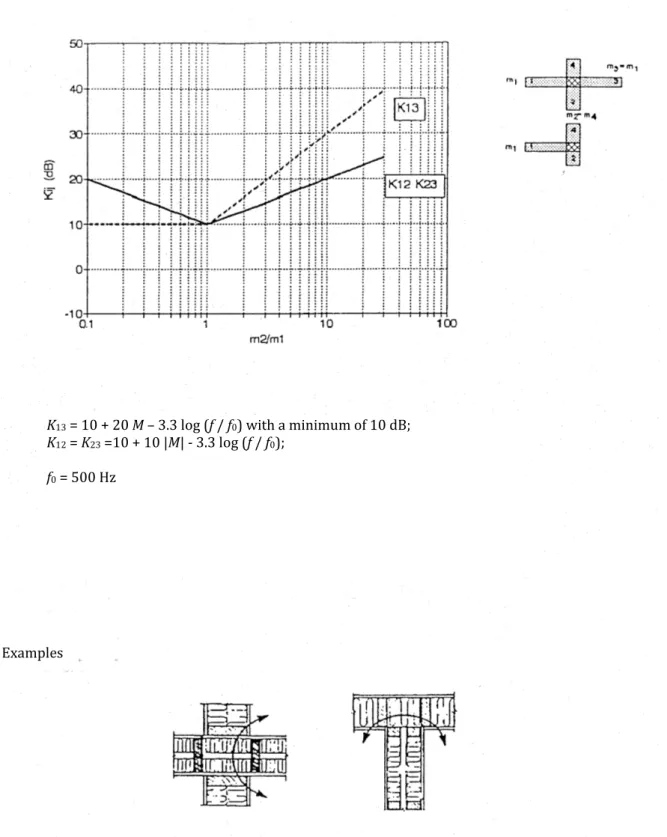
Figure 7.4 - Vibration reduction index of a node with lightweight double constructions.
Examples
K13 = 10 + 20 M – 3.3 log (f / f0) with a minimum of 10 dB; K12 = K23 =10 + 10 |M| - 3.3 log (f / f0);
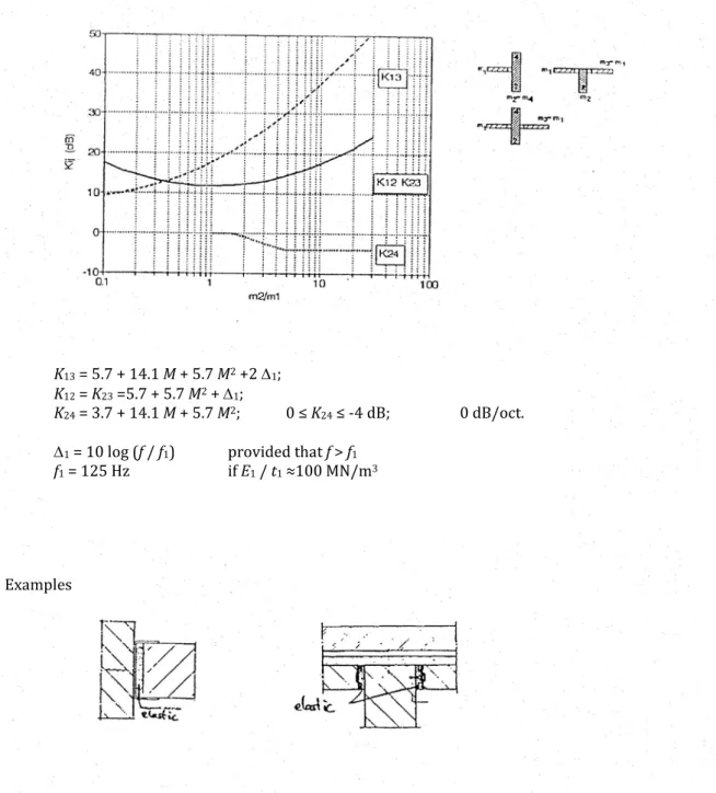
Figure 7.5 - Vibration reduction index of a node with flexible layers.
K13 = 5.7 + 14.1 M + 5.7 M2 +2 ∆1; K12 = K23 =5.7 + 5.7 M2 + ∆1;
K24 = 3.7 + 14.1 M + 5.7 M2; 0 ≤ K24 ≤ -4 dB; 0 dB/oct.
∆1 = 10 log (f / f1) provided that f > f1 f1 = 125 Hz if E1 / t1 ≈100 MN/m3
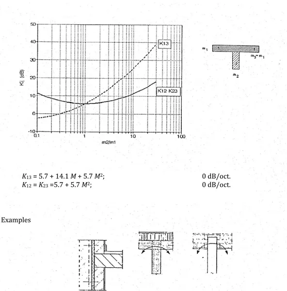
Figure 7.6 - Vibration reduction index of a rigid T-junction.
Examples
K13 = 5.7 + 14.1 M + 5.7 M2; 0 dB/oct.
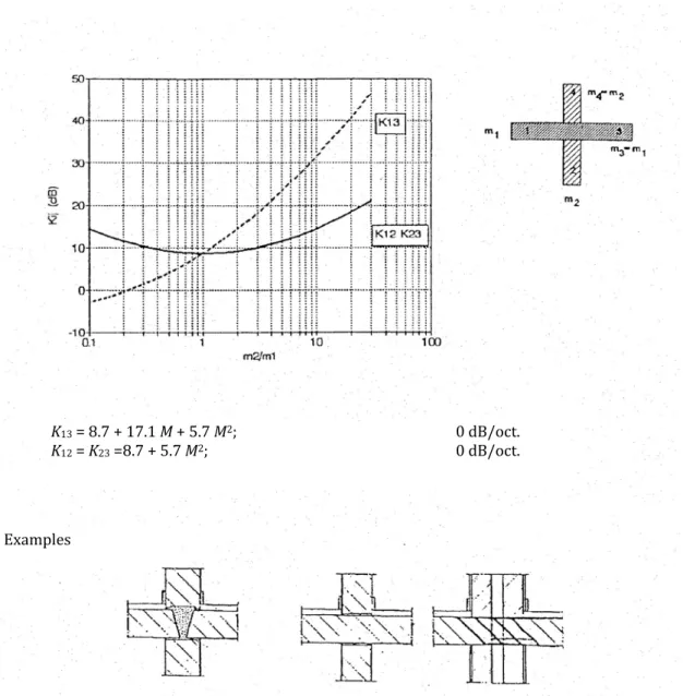
Figure 7.7 - Vibration reduction index of a rigid +-junction.
Examples
K13 = 8.7 + 17.1 M + 5.7 M2; 0 dB/oct.
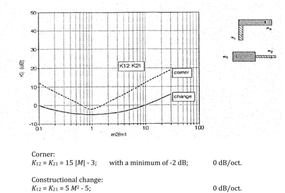
Figure 7.8 - Vibration reduction index of a corner or a constructional change.
7.2.3 Calculation scheme for obtaining total sound insulation between two rooms
The equations derived in the previous sections allow us to calculate the entire direct and flanking sound transmission from one room to another. For such a computation we distinguish several steps:
• Step 1: get acoustic data for all relevant construction elements and junctions by doing measurements, obtaining data from manufacturers or by making estimations;
• Step 2: fit the actual situation into the computation scheme using equations (7.15) and (7.16) (or (7.18)) and make simplifications (concerning the use or not of dampening) if necessary;
• Step 3: calculate Rd for the direct path through the partition wall and Rij for each flanking transmission
path using equation (7.19);
• Step 4: Add all transmission paths to obtain the sound insulation between both rooms, R’, which is calculated as /10 /10 ' 10log 10Rd 10Rij R = − − + −
∑
(7.22);• Step 5: Calculate the normalised sound reduction index, DnT, used by building codes and standards to
set limits to the sound transmission in buildings as 0 ' 10log 6 nT d V D R S T = + (7.23), with
V = the volume of the receiving room [m3] Sd = the surface area of the partition wall [m2]
Rd = the air-borne sound insulation of the direct partition wall/floor including front walls, etc. T0 = a reference reverberation time (=0.5 s for dwellings and 0.8 s for offices).
Corner:
K12 = K21 = 15 |M| - 3; with a minimum of -2 dB; 0 dB/oct.
Constructional change:
As a calculation example, we look at two adjacent and identical cubic rooms of 4 x 4 x 4 m3. The walls and
floors have identical mass, identical air-borne sound insulation values (Rd) and identical surface areas. The
junction between walls and floors are fixed +-junctions. This implies that Rij is identical for each flanking
transmission path, that m2 / m1 = 1 and thus M = 0 and that according to Figure 7.7 the vibration reduction
index, Kij, for each flanking transmission path is 8.7 dB (K13 = K12 = K23). For step 2, we neglect dampening,
as a result of which the air-borne sound insulation measured in a laboratory equals the one in practice (eq. (7.15)) and the value of the geometric correction factor a equals the value of the surface area of the respective construction wall (eq. (7.15) equals eq. (7.18)). For step 3, we can now use equation (7.19) to calculate the flanking sound reduction index for each transmission path. Since all transmission paths are identical in this simple example we only do this once:
4 4 10log 8.7 10log 14.7 2 2 4 i j d d d ij ij d ij R R S R R R K R l + + × ≈ + + = + + = +
For step 4, we first have to determine the number of (identical) transmission paths. Via each junction there can be 3 transmission paths and in total there are 4 junctions between both rooms. We thus have 12 identical transmission paths. All flanking and direct transmission paths can now be combines into one value using equation (7.22) as
( )
(
14.7 /10)
(
)
/10 /10 /10 14.7/10 ' 10log 10 Rd 12 10 Rd 10log 10Rd 12 10Rd 10 R = − − + ⋅ − + = − − + ⋅ − ⋅ − 10log 10Rd/10
(
1 12 1014.7/10)
10log 10Rd/10 10log 1 12 1014.7/10 1.5d
R
− − − −
= − ⋅ + ⋅ = − − + ⋅ = −
As a result in this particular case, the air-borne sound insulation between both rooms is only 1.5 dB worse due to flanking sound transmissions. In many other situations however the influence of flanking
transmissions can be much higher. Using the value for R’, finally, the normalised sound reduction index, DnT, can be calculated. This final step will be omitted here.
7.2.4 Extended calculation example
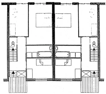
As an extended example, the computation scheme for determining the total sound transmission between two rooms will be demonstrated using an example from Braat-Eggen and Luxemburg (1993). This example deals with the sound insulation between two bed rooms on two sides of a wall which separates between two houses (Figure 7.9). The symbols and junction dampening are derived from section 7.2.2.
To be able to calculate the sound reduction between the two bed rooms, the following data is needed: • The air-borne sound insulation, Rd, and surface area, Sd, of the partition wall between both rooms;
• The air-borne sound insulation, Ri and Rj, and surface area, Si and Sj, of all adjoining walls/floors;
• The vibration dampening, Dij, of vibration reduction index, Kij, of all relevant junctions;
• The net volume of the rooms, V.
In this example both rooms are identical and have a volume of 30 m3. Sound insulation and surface area of the partition wall
The partition wall consists of 200 mm concrete, has a surface area of 10 m2 and a mass of 460 kg/m2. The
sound insulation of a 200 mm thick concrete wall equals
f [Hz] 125 250 500 1000 2000
Figure 7.9 - Plans of two adjoining row houses.
Sound insulation and surface area of the adjoining walls and floors
The floor and the ceiling consist of a 180 mm thick concrete slab including 30 mm surface layer. They have a surface area of 12 m2 and a mass of 471 kg/m2. The sound insulation of these concrete slabs equals
f [Hz] 125 250 500 1000 2000
R [dB] 41 46 55 63 70
The internal wall that perpendicularly connects to the partition wall consists of 70 mm thick gypsum blocks, has a surface area of 7.5 m2 and a mass of 67 kg/m2. The sound insulation of 70 mm thick gypsum
blocks equals
f [Hz] 125 250 500 1000 2000
R [dB] 29 29 26 32 41
The façade that connects to the partition wall consists of glass and a masonry cavity wall. It has a surface area of 5 m2 and a mass of 320 kg/m2. Since from a perspective of flanking transmission a cavity wall does
not act like such a wall, a fictive homogeneous wall is used with a mass equal to the mass of the inner leaf plus half of the mass of the outer leaf. The sound insulation of this modelled façade equals
f [Hz] 125 250 500 1000 2000
R [dB] 36 40 44 53 61
Junction dampening of the adjoining walls and floors
The junction dampening is determined using the mass ratios of the construction walls. In agreement with Figures 7.2 and 7.7 we get
m2/m1 M Kij Dij ≈ Kij + 5 Floor: fixed +-junction (Fig.7.7)
partition wall - floor (K23)
floor - partition wall (K12)
floor - floor (K13) 460/471=0.98 460/471=0.98 460/471=0.98 -0.01 -0.01 -0.01 8.7 8.7 8.7 14 14 14
Ceiling: fixed +-junction (Fig.7.7) partition wall - ceiling (K23)
ceiling - partition wall (K12)
ceiling - ceiling (K13) 460/471=0.98 460/471=0.98 460/471=0.98 -0.01 -0.01 -0.01 8.7 8.7 8.7 14 14 14 Interior walls: fixed +-junction (Fig.7.7)
partition wall - interior wall (K23)
interior wall - partition wall (K12)
interior wall - interior wall (K13)
460/67=6.87 460/67=6.87 460/67=6.87 0.837 0.837 0.837 12.7 12.7 27.0 18 18 32 Facade: T-junction (Fig.7.2)
partition wall - façade (K23)
façade - partition wall (K12)
façade - façade (K13) 460/320=1.44 460/320=1.44 460/320=1.44 0.158 0.158 0.158 11.6 11.6 6.6 17 17 12
Now that all relevant acoustic properties have been specified, we can proceed with the calculation. For the direct sound insulation between both rooms, we can immediately use the values of the concrete partition wall. It was specified as
f [Hz] 125 250 500 1000 2000
Rd [dB] 38 45 54 62 69
For the flanking sound transmission paths, we must calculate Rij for instance using equation
10log 2 i j ij d ij i j R R S R D S S + = + + .
Please observe that, since we use the simplified calculation of Dij from Kij (Dij ≈ Kij + 5), a small difference
occurs compared to the situation in which we would have used Dij ≈ Kij – 10 log (lij / √(SiSj)). Using
previous equation we calculate for each flanking transmission path the following values ceiling - partition wall / floor - partition wall
f [Hz] 125 250 500 1000 2000 Rd / 2 [dB] 19.0 22.5 27.0 31.0 34.5 Rfl / 2 [dB] 20.5 23.0 27.5 31.5 35.0 Dij [dB] 14.0 14.0 14.0 14.0 14.0 10 log (Sd / √(SiSj)) [dB] -0.4 -0.4 -0.4 -0.4 -0.4 Rfl-d [dB] 53.1 59.1 68.1 76.1 83.1
interior wall - partition wall
f [Hz] 125 250 500 1000 2000 Rd / 2 [dB] 19.0 22.5 27.0 31.0 34.5 Rint / 2 [dB] 14.5 14.5 13.0 16.0 20.5 Dij [dB] 18.0 18.0 18.0 18.0 18.0 10 log (Sd / √(SiSj)) [dB] +0.6 +0.6 +0.6 +0.6 +0.6 Rint-d [dB] 52.1 55.6 58.6 65.6 73.6
façade - partition wall f [Hz] 125 250 500 1000 2000 Rd / 2 [dB] 19.0 22.5 27.0 31.0 34.5 Rfac / 2 [dB] 18.0 20.0 22.0 26.5 30.5 Dij [dB] 17.0 17.0 17.0 17.0 17.0 10 log (Sd / √(SiSj)) [dB] +1.5 +1.5 +1.5 +1.5 +1.5 Rfac-d [dB] 55.5 61.0 67.5 76.0 83.5 partition wall - ceiling / partition wall - floor
f [Hz] 125 250 500 1000 2000 Rd / 2 [dB] 19.0 22.5 27.0 31.0 34.5 Rfl / 2 [dB] 20.5 23.0 27.5 31.5 35.0 Dij [dB] 14.0 14.0 14.0 14.0 14.0 10 log (Sd / √(SiSj)) [dB] -0.4 -0.4 -0.4 -0.4 -0.4 Rd-fl [dB] 53.1 59.1 68.1 76.1 83.1
partition wall - interior wall
f [Hz] 125 250 500 1000 2000 Rd / 2 [dB] 19.0 22.5 27.0 31.0 34.5 Rint / 2 [dB] 14.5 14.5 13.0 16.0 20.5 Dij [dB] 18.0 18.0 18.0 18.0 18.0 10 log (Sd / √(SiSj)) [dB] +0.6 +0.6 +0.6 +0.6 +0.6 Rd-int [dB] 52.1 55.6 58.6 65.6 73.6 partition wall - façade
f [Hz] 125 250 500 1000 2000 Rd / 2 [dB] 19.0 22.5 27.0 31.0 34.5 Rfac / 2 [dB] 18.0 20.0 22.0 26.5 30.5 Dij [dB] 17.0 17.0 17.0 17.0 17.0 10 log (Sd / √(SiSj)) [dB] +1.5 +1.5 +1.5 +1.5 +1.5 Rd-fac [dB] 55.5 61.0 67.5 76.0 83.5 ceiling - ceiling / floor - floor
f [Hz] 125 250 500 1000 2000
Rfl [dB] 41.0 46.0 55.0 63.0 70.0
Dij [dB] 14.0 14.0 14.0 14.0 14.0
10 log (Sd / √(SiSj)) [dB] -0.8 -0.8 -0.8 -0.8 -0.8
Rfl-fl [dB] 54.2 59.2 68.2 76.2 83.2 interior wall - interior wall
f [Hz] 125 250 500 1000 2000 Rint [dB] 29.0 29.0 26.0 32.0 41.0 Dij [dB] 32.0 32.0 32.0 32.0 32.0 10 log (Sd / √(SiSj)) [dB] +1.2 +1.2 +1.2 +1.2 +1.2 Rint-int [dB] 62.2 62.2 59.2 65.2 74.2 façade - façade f [Hz] 125 250 500 1000 2000 Rf [dB] 36.0 40.0 44.0 53.0 61.0 Dij [dB] 12.0 12.0 12.0 12.0 12.0 10 log (Sd / √(SiSj)) [dB] +3.0 +3.0 +3.0 +3.0 +3.0 Rf-f [dB] 51.0 55.0 59.0 68.0 76.0
Combining all 13 (1 direct and 12 flanking) transmission paths according to equation (7.22) then results in the total sound insulation between both rooms. The results are presented below.
Summary of all transmission paths and combination into one total value f [Hz] 125 250 500 1000 2000 Rd [dB] 38 45 54 62 69 R floor - d [dB] 53.1 59.1 68.1 76.1 83.1 R ceiling - d [dB] 53.1 59.1 68.1 76.1 83.1 R interior wall - d [dB] 52.1 55.6 58.6 65.6 73.6 R facade - d [dB] 55.5 61.0 67.5 76.0 83.5 Rd - floor [dB] 53.1 59.1 68.1 76.1 83.1 Rd - ceiling [dB] 53.1 59.1 68.1 76.1 83.1 Rd - interior wall [dB] 52.1 55.6 58.6 65.6 73.6 Rd - facade [dB] 55.5 61.0 67.5 76.0 83.5 Rfloor - floor [dB] 54.2 59.2 68.2 76.2 83.2 Rceiling - ceiling [dB] 54.2 59.2 68.2 76.2 83.2
Rinterior wall - interior wall [dB] 62.2 62.2 59.2 65.2 74.2 Rfacade - facade [dB] 51.0 55.0 59.0 68.0 76.0
R’ [dB] 36.8 43.0 49.8 57.4 65.0
Rd - R’ [dB] 1.2 2.0 4.2 4.6 4.0
With a volume of 30 m3 and a surface area of the partition wall of 10 m2, the normalised sound reduction
index, DnT, between both rooms can now be calculated according to equation (7.23). The results are
presented in the table below
normalized sound reduction index and standardised values
f [Hz] 125 250 500 1000 2000
DnT [dB] 36.8 43.0 49.8 57.4 65.0
standardised values [dB] 34.0 43.0 50.0 53.0 54.0
difference [dB] +2.8 0.0 - 0.2 +4.4 +11.0
The air-borne sound insulation index, Ilu, can now be calculated using the difference between DnT and the
standardised values. It is the smallest value of the following three situations:
a.) the average value of the five differences in sound insulation (125 Hz to 2000 Hz), rounded to the closest integer; here: (+2.8+0.0-0.2+4.4+11.0)/5 = 3.6 dB = +4 dB;
b.) the average value of the two algebraically smallest differences in sound insulation added with 2 dB, rounded to the closest integer; here: (+0.0-0.2)/5 + 2.0 = 2.0 dB = +2 dB;
c.) the algebraically smallest difference in sound insulation added with 4 dB, rounded to the closest integer; here: -0.2 + 4.0 = 3.8 dB = +4 dB;
Ilu here thus equals +2 dB.
The characteristic air-borne sound insulation index, Ilu;k, can finally be computed from
; 10log 6 1 2 10log 6 0.5 1030 1 1 ( 0 0.5 ) lu k lu o d V I I dB T s T S = − − = − − = = ⋅ ⋅
7.3
Flanking Sound Transmission: Structure-Borne Excitation
In the previous sections only air-borne excitation of construction elements was considered. Such air-borne excitation might be caused by a radio, a television, a human voice, etc. In practice however structure-borne excitation, for instance caused by a washing machine, other equipment or women walking on high heels, must sometimes be considered as well. In this section the equation describing flanking sound transmission
flanking transmission, the transmission of waves from one room to the other is identical. The only difference lies in the way the construction is caused to vibrate.
Using a similar procedure as in section 7.2.1 and again using the principle of force reciprocity, the
governing equations for flanking transmission caused by impact noise can be derived. The sound pressure level in the receiver room, Ln;ij, caused by element i in the receiver room with Ln;ii equals
; ; ; i2 j ij 10log j n ij n ii n ii j i R R S L L L R D S − = − ∆ − ∆ + − − (7.24a).
As an estimate, neglecting dampening, we can also simplify this equation as ; ; ; i2 j 10log i n ij n ii n ii j ij ij R R S L L L R K l − = − ∆ − ∆ + − − (7.24b).
It is important finally to realise that due to the way the structure is excited, usually only two flanking transmission paths exist: Ff and Fd in case a floor, ceiling or parallel wall is excited. Based upon these paths, the total sound pressure level in the receiver room can be calculated from
(
;/10)
; 10log 10Ln ij p r
L =
∑
(7.25).7.4 Flanking Sound in Practice
7.4.1 Building constructions that separate between dwellings
Flanking sound transmission is particularly important for the sound proofing between two dwellings. Flanking transmissions lead to a reduction of the total sound insulation of 1 to 2 dB. This reduction in fact needs to be compensated with a better acoustic performance of the direct partition wall because
performance requirements are set for Ilu;k which includes both direct and flanking transmissions. The
calculation example of section 7.2.4 shows us that this indeed is the case. The sound insulation of the 12 flanking transmission paths combined was calculated as
f [Hz] 125 250 500 1000 2000
R [dB] 43.0 47.3 51.9 59.2 67.2
This sound insulation must be seen against the sound insulation of the direct partition wall which was given as
f [Hz] 125 250 500 1000 2000
R [dB] 38 45 54 62 69
As can be seen, in the lower frequency range (125 to 250 Hz), the direct path is most dominant for the total sound transmission between both rooms; in the middle and higher frequency range (higher than 500 Hz), the flanking paths are dominant. If we look in more detail at the calculation results in section 7.2.4, we see for the frequencies 500 to 2000 Hz that especially the transmission paths related to the lightweight interior wall reduce the total sound insulation. At the lower frequencies also the transmission via the façade has its share. If the lightweight interior wall were perfectly de-coupled from the partition wall, as shown in Figure 7.10, and the sound insulation of the transmission path façade – façade alone played a role, R’ and thus DnT at 500 Hz would never be higher than -10 log (10-5.4 + 10-5.9) = 52.8 dB. The
determining sound insulation difference would then become approximately 3 dB higher (52.8 – 49.8). And as a result, Ilu;k would become +4 dB instead of +1 dB. An even better improvement can be obtained by also
Figure 7.10 – Flexible connection of a lightweight interior wall to a partition wall separating between two dwellings. Materials of the interior wall can be cellular concrete, lightweight concrete, gypsum blocks etc.
More details concerning the connection of flanking walls to partition walls in residential buildings can be found in the Dutch Guideline NPR 5070 “Geluidwering in woongebouwen. Voorbeelden van wand- en vloerconstructies” (“Sound proofing in residential buildings. Examples of wall and floor constructions”). 7.4.2 Effect of lightweight walls in front of massive walls
A construction often used to improve the air-borne sound insulation of walls is a lightweight wall placed in front of the original wall, or a suspended ceiling or a floating screed on top of a floor. The essence of these additions is that they are hardly connected to the original wall, floor or ceiling thus creating an
unconnected cavity construction. As a result of this type of construction the dynamic behaviour of the original wall, floor is ceiling is not affected by the addition. For flanking sound transmission the effect of this addition can thus be neglected and the modeling described in previous sections can be used. The additional construction however does have an effect on the direct air-borne sound insulation of the construction. This effect can be described as a reduction ∆R of the direct partition wall or of the flanking construction element.
7.4.3 Aluminium-glass facades
A typical example of a curtain wall facade onto which a separation wall is connected is shown in Figure 7.11. Resulting from the desire for flexibility, the façade is designed in such a way that for instance at every 1.80 m or even 0.90 m a separation wall can be connected to the façade. This interior wall then connects to the aluminium mullions of the façade and not to for example a concrete column as part of the load-bearing structure. The total façade construction then acts as a flanking surface. Despite the fact that the
requirements on the sound insulation between offices is 8 to 14 dB less than compared to dwellings (Table 7.1), the influence of the sound transmission via the façade is noticeable and important to consider. Figure 7.2 for instance gives for a lightweight façade construction with mseparation wall / mfacade = 1 a vibration
reduction index, K13, of 5 dB and thus D13 of approximately 10 dB. Because however the façade is not
monolithic but consists of several interconnected parts allowing certain flexibility, Figure 7.2 gives a very rough estimate of the junction dampening. It is therefore wise to use laboratory measurements in stead.
room type minimum required air-borne sound
insulation index for
accommodation space circulation space normal cellular offices
cellular offices with privacy open-plan offices consultation rooms meeting rooms -14 -8 -14 -14 -8 -26 -20 -26 -26 -20
Figure 7.11 - Aluminium curtain wall suitable for connection with interior walls.
For determining the flanking sound transmission in a laboratory the following equation applies
; ; 10log o 10log f p s p r r o S l R L L A l = − + + (7.26), with
Rf = the flanking sound reduction in a laboratory [dB] S0 = a reference surface area (=10 m2)
l = the length of the mutual line between the partition wall and the flanking wall [m] l0 = a reference length (=2.8 m)
Ar = the sound absorption in the receiver room [m2 sabin].
The flanking sound transmission reduction occurring in an actual non-laboratory situation can now be calculated from 10log d 10log ij ij f o o l S R R S l = + + (7.27).
Research has shown that the total surface area of the flanking façade on both the sending and the receiving side is not relevant. The surface of the façade further than about 2.5 m away from the interior wall no longer participates in the flanking sound transmission. Measurements have shown that the sound transmission is mainly determined by the surface of the façade which continues from the interior wall to the second mullion at most; each mullion also adds a certain amount of dampening. The junction
dampening between mullion and glass can be increased if an operable window in stead of a fixed glass sheet is used (Figure 4.12); the improvement of the flanking sound reduction can be about 6 dB in that case since the material used for closing the gaps dampens the vibrations. In stead of connecting the elements of
the aluminium-glass façade rigidly, the posts onto which the interior wall connects can also be dilated. This also gives a performance improvement of about 7 dB compared to the rigid construction.
Curtain walls are mostly constructed of tubular profiles giving stiffness and strength to the façade. These tubular profiles, if they are situated on the inside of the façade, are so to speak part of the direct separating construction. This implies that in case of a mullion with a depth of 80 mm and a room depth of 5.2 m approximately 1.5% of the partition area consists of this tubular profile. The sound insulation of such tubular profiles is negatively influenced by resonances inside its cavity. For particularly the bigger profiles this resonance occurs in the mid-frequency range which is especially important for Ilu. An effective means
to improve the sound insulation of the tubular profile is to increase its mass or to add absorption material in its cavity.
Table 7.2, taken from (Meyer and Neumann, 1979), finally, presents an overview of the flanking sound reduction, Rf, of aluminium-glass façades.
7.5 Literature
P.E. Braat-Eggen and L.C.J. van Luxemburg (1993), Geluidwering in de woningbouw, SMD / Waltman, Leiden E. Gerretsen (2001), Constructiegeluid in gebouwen - modelvorming in de bouwakoestiek, Lecture notes for
7S650, Faculty of Architecture Building and Planning, Eindhoven University of Technology.
F.P. Mechel (1980), “Schall-Längsdämmung von Deckenverkleidungen”, Bau- und Wohnforschung F1630. H.A. Metzen (1997), “Berechnungsmethoden für die Luft und Trittschalldämmung in Gebäuden”, WKSB 40
(17).
E. Meyer and E.G. Neumann (1979), Physikalische und Technische Akustik, 3rd ed, Vieweg, Braunschweig. Stichting Bouwresearch (1982), Pannendakconstructies - het weren van lawaai, SBR-report B3-5, SBR,
Rotterdam.
H.L.S. Vercammen and Th.W. Scheers (1994), “Geluidisolatie in de utiliteitsbouw”, NAG Journaal 122. G. Vermeir (1991-1996), Bouwakoestiek - Fysische principes geluidtransmissie geluidafstraling, Hogere
Cursus Akoestiek, Antwerpen.
G.S. Bron-van der Jagt, E. Gerretsen, S.S.K. Lentzen (2010), “Lichtgewicht (woon)gebouwen. Deel 1: voorspelling van lucht- en contactgeluidisolatie tussen ruimten”, Bouwfysica 21 (4): 2 - 9.