Bond behaviour of externally applied reinforcement
for the case of I-shaped concrete cross-sections
Tom Claeys
Student number: 01406845
Supervisor: Prof. dr. ir. Stijn Matthys
Counsellor: Muhammad Arslan Yaqub
Master's dissertation submitted in order to obtain the academic degree of Master of Science in Civil Engineering
Bond behaviour of externally applied reinforcement for
the case of I-shaped concrete cross-sections
Tom Claeys
Student number: 01406845
Supervisor: Prof. Dr. ir. Stijn Matthys,
Counsellor: Muhammad Arslan Yaqub
Master's dissertation submitted in order to obtain the academic degree of Master of Science in Civil Engineering
Academic year: 2019 – 2020
IV
Permission for personal use
“The author gives permission to make this master dissertation available for consultation
and to copy parts of this master dissertation for personal use. In all cases of other use, the
copyright terms have to be respected, in particular with regard to the obligation to state
explicitly the source when quoting results from this master dissertation."
V
Preface
Before you lies the master dissertation “Bond behaviour of externally applied reinforcement for the case of I-shaped concrete cross-sections”. This is the result of a journey that started in September 2019 and ended in June 2020. It was a challenging way, due to several unforeseen circumstances such as the COVID-19 pandemic. However, this journey was very educational. Of course this work was not possible without the help of several people, and I would like to take this moment to thank them.
First of all, my supervisor Prof. dr. ir. Stijn Matthys deserves a thank you. Thanks to him I got the unique chance to study this topic. His guidance and feedback during the monthly meetings was very useful for the research performed in this master dissertation. His understanding for the difficulties due to the COVID-19 pandemic was very much appreciated as well.
Secondly, I would like to thank my counsellor Muhammad Arslan Yaqub. He was always willing to help during the whole year. In addition, I am very grateful for his effort to proofread this dissertation, to further improve its quality.
With regard to the experimental testing, I would like to thank the staff of the Magnel Laboratory for all their assistance. Thanks to Tommy De Ghein for finding place in the planning, Tom Stulemeijer and Dieter Hillewaere for their help during the casting of the concrete, Stefan De Bock for his effort to create the complicated formwork, Peter Van Den Bussche for his assistance in recording the test data and Jens Mortier to order all the necessary material.
Also, I would like to offer my special thanks to my sister. During the whole year she was willing to help me with her knowledge and she was always there to support me. In addition, I would like to thank her for reading and correcting my master thesis as well.
Finally, I would like to thank my parents. They gave me the opportunity to start and complete these studies, and they have supported me relentlessly during the complete six years.
VI
Bond behaviour of externally applied reinforcement for
the case of I-shaped concrete cross-sections
Tom Claeys
Academic year 2019-2020 Ghent University
Faculty of Engineering and Architecture
Department: Department of structural engineering and building materials
Abstract
This master dissertation studies the bond behaviour between externally applied reinforcement and a concrete section. The research focuses on shear-strengthening applications. Therefore small I-sections are tested. A literature study is performed to obtain understanding about the problem. A study of different anchorage types, bond-slip tests and numerical modelling methods for FRP-concrete debonding behaviour is performed.
A numerical model is made in DIANA 10.3 to investigate this behaviour. First, a rectangular 2D-model of a pull-off test is analysed and calibrated by experimental results. A cohesive bond approach is shown to have the best performance. It is found that changing the width or the thickness of the FRP equally, has a different effect on the bond behaviour. Providing an anchorage is proved to be useful, however, the effectiveness depends on the failure mode.
Further, the model for an I-shaped section is created. Different configurations of the I-shape are tested numerically. Several issues when modelling the I-shape are, however, encountered and demonstrated in the report. The design of a filling block on the I-shape is modelled as well. The filling block can have an advantageous effect on the bond behaviour, however, it has to be modelled properly.
Keywords: externally applied reinforcement, fibre reinforced polymer, I-shaped concrete cross-section, shear strengthening, anchorages
VII
Bond behaviour of externally applied reinforcement
for the case of I-shaped concrete cross-sections
Tom Claeys
Supervisors: Prof. dr. ir. Stijn Matthys, Muhammad Arslan Yaqub
Abstract: In the present work, the bond behaviour between
externally applied reinforcement and a concrete I-section is studied. The research focuses on shear-strengthening applications. Therefore, small I-sections are tested. A literature study is performed to obtain understanding about the problem and to study different anchorage types.
A numerical model is made in DIANA 10.3 to investigate the bond behaviour. First, a rectangular 2D-model of a pull-off test is analysed and calibrated by experimental results. A cohesive bond approach is shown to have the best performance. It is found that changing the width or the thickness of the FRP equally, has a different effect on the bond behaviour. Providing an anchorage is proved to be useful, however, the effectiveness depends on the failure mode.
An I-shaped section is modelled as well. Different configurations of the I-shape are tested numerically. Several issues when modelling the I-shape, however, are encountered. Finally, the design of a filling block on the I-shape is modelled. The filling block can have an advantageous effect on the bond behaviour, however, it has to be modelled properly.
Keywords: externally applied reinforcement, fibre reinforced
polymer, I-shaped concrete cross-section, shear strengthening, anchorages
I. INTRODUCTION
It is generally known that concrete structures, such as buildings and bridges, degrade during their lifetime because of durability issues, vandalism, ... Sometimes also a change in use or increase of the expected loads is causing the degradation. In order to obtain the aimed service life of a structure, it is more feasible to execute strengthening techniques than to completely demolish and rebuild the structure. Strengthening of beams can be done in order to increase the flexural strength, shear strength, ... One of the most commonly used strengthening methods is the application of fibre reinforced polymers (FRP) as external reinforcement. FRP consists of high strength fibres embedded in a polymer matrix. Carbon fibres are most commonly used in construction industry because of their excellent mechanical properties [1].
Shear strengthening is often required since shear failure results in brittle collapse of the structure. Shear strengthening with FRP is usually done by applying the FRP in a U-shape around the concrete cross-section. Different failure modes happen in FRP-strengthened concrete members. The most common one is concrete cover
separation, due to the low tensile strength of concrete [2]. For I-shaped concrete cross-sections, an additional difficulty is introduced. Since FRP works in tension, it searches for the shortest possible length and consequently debonding starts from the internal angles of the I-shape (Figure 1).
Figure 1: Critical zones for early debonding of FRP on I-shape
In order to prevent the early debonding of the FRP, an anchorage can be used. Many different anchorage types were already designed, however, little knowledge is provided about their relative performance. Several commonly proposed anchorages are discussed here. First of all, a transverse CFRP strip can be applied [3]. This anchor is reliable, but has a rather low efficiency. As extension on this type of anchorage, a patch anchor was developed [4]. A patch anchor consists of 2 two-directional FRP-sheets. One sheet is applied under the U-shaped FRP and the other one on top. This way of anchoring showed high performance and is also reliable. Secondly, spike anchors are a popular anchorage method (Figure 2) [3]. Spike anchors consist of an FRP-rope which is anchored inside the concrete and spread out over the applied FRP-sheet. This anchor was proved to have a rather good efficiency.
VIII
Figure 2: Spike anchor [3]
As third, a mechanical anchor can be constructed. Various configurations of mechanical anchors have been used already [5,6]. It consists mainly of a steel plate which is pressed on the FRP-sheet and fixed by bolts. This anchor does not show the best performance, however, it is easy to apply and therefore quite popular.
A fourth way of anchoring the FRP-sheet is by using a near-surface-mounted method [7]. A groove is cut inside the concrete specimen in which the FRP is epoxied. This anchorage type shows good effectiveness. A variant on NSM anchorage is substrate strengthening [8]. In substrate strengthening a small groove is cut in the concrete, epoxied and then the FRP-sheet is applied on top of this (Figure 3).
Figure 3: Substrate strengthening [8]
It is clear that different possible bonding procedures exist in literature. In this work, various arrangements of bonding CFRP on concrete, with and without anchors, were numerically modelled and analysed to investigate their performance.
II. NUMERICAL MODEL
A. Rectangular block
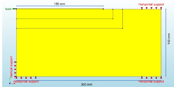
First, a single shear type test on a rectangular block was modelled in DIANA 10.3. The block was supported by 3 horizontal and 1 vertical roller supports (Figure 4). The concrete block was divided in different pieces for the mesh elements. The load was applied as a prescribed displacement at the left side of the FRP. The FRP had a thickness of 1.4 mm. In the 2D-model, also the width of the elements
was defined. The FRP had a width of 100 mm and the concrete block had a width of 140 mm.
Figure 4: Geometry and boundary conditions of rectangular model
The basic material properties of the concrete and FRP are given in Table 1 and Table 2. The actual Young’s modulus of FRP was equal to 209 GPa. This value was divided by 2 since it was chosen to model the FRP twice as thick as its nominal thickness.
Table 1: Material properties concrete
fc 53.7 MPa
ft 3.86 MPa
Ec 37 GPa
νc 0.15
Gf 188 N/m
Table 2: Material properties FRP
Ef 105 GPa
νf 0.35
A total strain crack model was used for concrete. In this model, the concrete tensile strength was defined by the curve of Hordijk and the concrete compression strength by the curve of Thorenfeldt. The reduction model of Vecchio and Collins from 1986 was introduced to allow for reduction of lateral cracking of concrete [9]. A cohesive zone method was used to model the interface. For this method, cohesive zone elements with zero thickness were introduced between FRP and concrete. These elements were given initial values for the stiffness modulus and the shear stiffness modulus. These values were obtained by following formulas respectively:
kn= EfEc hj(Ef− Ec) kt= GfGc hj(Gf− Gc) With: G =2(1+ν)E
The thickness hj represents the thickness of the joint, i.e. the
thickness of the adhesive layer, and was estimated as 1 mm. The corresponding values of the stiffness and shear stiffness modulus were respectively 44.96 GPa/mm and 13.22 GPa/mm. On these elements a bond-slip relation was defined. A bilinear-bond-slip law was used, defined as follows [10]:
τmax= 0.165fc= 8.86 MPa
IX
smax= −0.002fc+ 0.302 = 0.1946 mm
The FRP was modelled as a linear elastic isotropic composite material.
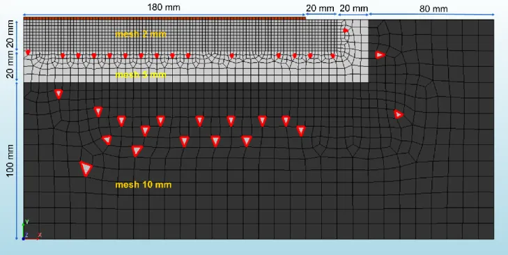
A physical nonlinear analysis was executed in DIANA. Load steps of 0.002 mm were defined. The Quasi-Newton method was used to solve the system of equations. An arc-length method was introduced for possible snap-through behaviour. The energy norm was used as convergence criterion. A mesh study was performed to obtain a good estimation of the failure load. Once the load was changing with less than 2% between different mesh sizes, the mesh was acceptable. A zone with mesh sizes of 2, 5 and 10 mm was defined (Figure 5). The main mesh element was CQ16M, a quadratic element consisting of 8 nodes [9]. The secondary mesh element was CT12M (highlighted in red in Figure 5). This is a triangular element consisting of 6 nodes. For the interface, the line-mesh CL12I was introduced, consisting of 6 nodes.
Figure 5: Mesh for rectangular specimen
B. I-shape
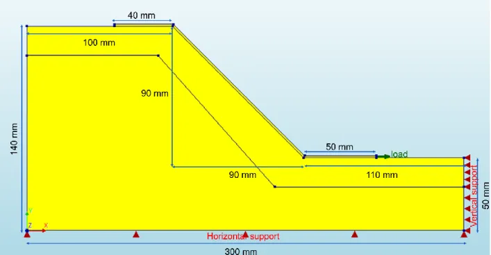
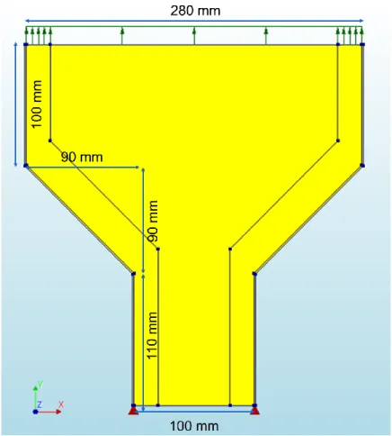
A simplified model of ¼ of an I-shaped cross-section was made (Figure 6). A similar approach was followed as for the rectangular block. The same material models and properties were used. The horizontal projected bond length of the FRP was 180 mm. However, the load was now applied on the right side of the FRP, going to the right. The roller supports cover the complete bottom and right side of the specimen. The mesh was determined similar to the previous case: a zone of 20 mm from the interface was defined with mesh sizes of 2 mm. After this zone a gradual increase to sizes of 10 mm was used. The mesh elements were the same as well as the analysis method.
Figure 6: Geometry and boundary conditions of I-model
Another model of the I-shape was made as well, in which half of the I-shape was created (Figure 7). The geometry and materials were again equal. The different approach consisted of applying the load at the top of the concrete and by only fixing the FRP at the bottom. Moreover, FRP was applied over the whole length.
Figure 7: Model of 1/2 I-shape
Four cases with straightened FRP over an I-shape were investigated as well. First, the FRP was applied on the flange of the specimen. Secondly, the top corner of the flange was rounded and the FRP was elongated over the top.
In the third and fourth case, a filling block was used. In the third case, a filling block with the same properties as the concrete was introduced. An adhesive layer was modelled in between (Figure 8). The fourth case had a perfect bond between the filling block and the I-shape. The properties of a cellular concrete block [11] were introduced for the filling block.
Figure 8: Numerical model of I-shape with FB and adhesive layer
III. RESULTS AND DISCUSSION
A. Rectangular block
The model was calibrated by comparison with experimental test results from [12]. In this article, the same experiments were executed twice. One of these experiments had the same properties as described before. The failure loads were equal to 27.8 and 31.7 kN. The failure load obtained by the numerical model was 28 kN. The strain curves (Figure 9) were very similar to the ones obtained by the experiments. The values of the bond stress-slip curves showed good agreement with
X
the experimental results as well (Figure 10). The slip was defined as the displacement in the FRP while the bond stress was determined by taking dx= 4 mm in following method:
τ(x) = tf
σf(x +dx2) − σf(x −dx2)
dx Where: tf= thickness of the FRP-sheet
σf(x + dx
2)= normal stress in FRP-sheet at x+dx/2
σf(x − dx
2) = normal stress in FRP-sheet at x-dx/2
Figure 9: Strain curves for rectangular block
Figure 10: Bond-slip curves for rectangular block
The width and the thickness of the FRP-sheet were varied. Widths of 50, 75 and 100 mm and thicknesses of 0.7, 1.05 and 1.4 mm were applied. The load-displacement curves for these cases are given in Figure 11 and Figure 12. It was found that for a lower width or thickness the failure load decreased, but the corresponding displacement increased. If the width of the FRP was reduced equally as the thickness, the curves were similar. It was also found that the capacity of the FRP was used more when the width or thickness was reduced. For all cases, except for the case of 50 mm width, concrete cover separation was observed, together with concrete cracking at the loading end, as shown in Figure 13. In the other case debonding along the bond-slip interface was observed, which is also shown on Figure 13. When bond-slip interface failure occurred, the obtained bond-slip curves were exactly the same as the one entered in the cohesive elements. The effective bond length was estimated from the bond-slip curve as 89.5 mm [1]. When the thickness was reduced, the effective
bond length is reduced as well. In all cases, the bond length was clearly larger than the effective bond length. The failure load increased linearly within the same failure mode for different widths, although for different thicknesses this was not the case.
Figure 11: Load-displacement curves for different FRP widths
Figure 12: Load-displacement curves for different FRP thicknesses
Figure 13: Horizontal displacements for concrete cover separation (top) and interface debonding (bottom)
An anchorage was modelled as well. This was done by connecting the translations at the last 40 mm of the FRP. When an FRP-sheet of 100 mm and 1.4 mm thick was used, a small effect was found as the concrete specimen broke in two, with a crack starting at the free end of the FRP. However, when the anchorage was applied with 50 mm
XI
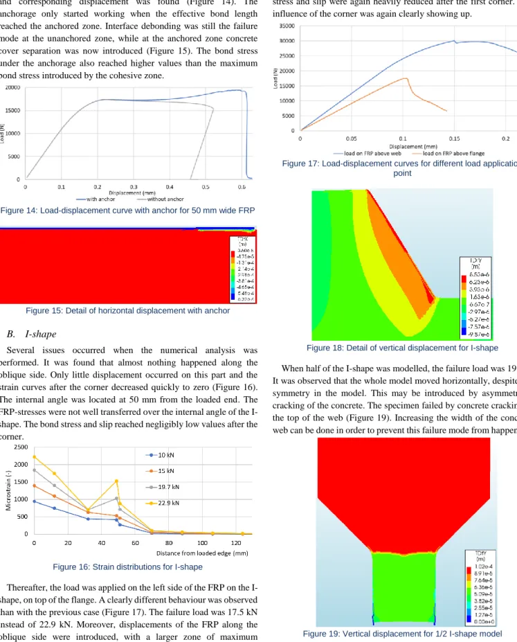
wide FRP, a significant increase of the failure load (17.4 to 19.4 kN) and corresponding displacement was found (Figure 14). The anchorage only started working when the effective bond length reached the anchored zone. Interface debonding was still the failure mode at the unanchored zone, while at the anchored zone concrete cover separation was now introduced (Figure 15). The bond stress under the anchorage also reached higher values than the maximum bond stress introduced by the cohesive zone.
Figure 14: Load-displacement curve with anchor for 50 mm wide FRP
Figure 15: Detail of horizontal displacement with anchor
B. I-shape
Several issues occurred when the numerical analysis was performed. It was found that almost nothing happened along the oblique side. Only little displacement occurred on this part and the strain curves after the corner decreased quickly to zero (Figure 16). The internal angle was located at 50 mm from the loaded end. The FRP-stresses were not well transferred over the internal angle of the I-shape. The bond stress and slip reached negligibly low values after the corner.
Figure 16: Strain distributions for I-shape
Thereafter, the load was applied on the left side of the FRP on the I-shape, on top of the flange. A clearly different behaviour was observed than with the previous case (Figure 17). The failure load was 17.5 kN instead of 22.9 kN. Moreover, displacements of the FRP along the oblique side were introduced, with a larger zone of maximum
displacement around the internal angle (Figure 18). However, the bond stress and slip were again heavily reduced after the first corner. The influence of the corner was again clearly showing up.
Figure 17: Load-displacement curves for different load application point
Figure 18: Detail of vertical displacement for I-shape
When half of the I-shape was modelled, the failure load was 19 kN. It was observed that the whole model moved horizontally, despite the symmetry in the model. This may be introduced by asymmetrical cracking of the concrete. The specimen failed by concrete cracking at the top of the web (Figure 19). Increasing the width of the concrete web can be done in order to prevent this failure mode from happening.
XII
For the first case with straightened FRP, it was found that the failure load was a bit lower than for the rectangular specimen, which can be explained by the bond length. Although the bond length was estimated to be slightly larger than the effective bond length, still a small increase in load was possible (24.4 instead of 28 kN). When the top corner of the flange was rounded and the FRP was elongated over the top (second case), again the same failure load was found, this indicates that probably a similar issue as with the I-shape was present.
When the third and fourth case were compared, it was found that the block with worse mechanical properties had a lower failure load (Figure 20), due to early debonding of the FRP on the filling block, introduced by filling block cover separation. However, in the other case, debonding started from the adhesive layer. Since the adhesive layer was only present after the effective bond length, this didn’t have a significant influence on the failure load.
Figure 20: Load-displacement curves with FB's
IV. CONCLUSION
Numerical modelling of bond-slip tests for FRP-concrete behaviour was performed. It was found that a different width or thickness of the FRP-sheet didn’t have the same influence on the results. In some cases different failure modes were found. However, the failure load was in all cases close to each other. Applying an anchorage showed to improve the failure load, however, the effectiveness of the anchor depended on the failure mode.
Making a simplified model of an I-shape showed to be rather difficult. Care should be taken on the boundary conditions, on the load application and on the behaviour along the oblique side of the specimen. Due to the presence of displacements perpendicular to the symmetrical axis, it was concluded that some effects introduce asymmetry, probably due to the cracking behaviour of the concrete.
A filling block proved to be a useful method to bond the FRP. However, the properties of the filling block and the location of the adhesive layer should be chosen carefully.
V. FURTHER RECOMMENDATIONS
Experimental testing should be executed to define the relative performance of different anchorages on an I-shape. For the numerical modelling, a convenient way to model an I-shape has to be defined. Moreover, more research towards the proper numerical modelling of anchorages has to be executed.
VI. REFERENCES
[1] S. Matthys et al., "Externally applied FRP reinforcement for concrete structures " in "Bulletin 90," fib, Switzerland, 2019. [2] C. Chen, L. Cheng, L. Sui, F. Xing, D. Li, and Y. Zhou, "Design method of end anchored FRP strengthened concrete struct," Elsevier- Engineering structures, no. 176, pp. 143-158, 2018.
[3] F. Ceroni and M. Pecce, "Evaluation of Bond Strength in Concrete Elements Externally Reinforced with CFRP Sheets and Anchoring Devices," (in English), Journal of Composites for Construction, Article vol. 14, no. 5, pp. 521-530, Sep-Oct 2010.
[4] R. Kalfat, R. Jumaah, R. Al-Mahaidi, K. Abdouka, and J. Hashemi, "Post-Tensioned Concrete Beams Strengthened in Shear Using Fiber-Reinforced Polymer Laminates and Patch Anchors," Journal of
Composites for Construction, vol. 24, no. 2, Apr 2020.
[5] M. Murphy, A. Belarbi, and S. W. Bae, "Behavior of prestressed concrete I-girders strengthened in shear with externally bonded fiber-reinforced-polymer sheets," (in English), Pci Journal, Article pp. 63-82, Sum 2012.
[6] E. Oller, M. Pujol, and A. Marí, "Contribution of externally bonded FRP shear reinforcement to the shear strength of RC beams,"
Elsevier- Composites Part B, no. 164, pp. 235-248, 2018.
[7] K. N. Rahal and H. A. Rumaih, "Tests on reinforced concrete beams strengthened in shear using near surface mounted CFRP and steel bars," (in English), Engineering Structures, Article vol. 33, no. 1, pp. 53-62, Jan 2011.
[8] S. V. Grelle and L. H. Sneed, "Review of Anchorage Systems for Externally Bonded FRP Laminates," (in English), International
Journal of Concrete Structures and Materials, Review vol. 7, no. 1,
pp. 17-33, Mar 2013.
[9] J. Manie and D. Ferreira. "Diana user's theory manual." DIANA FEA bv.
https://dianafea.com/manuals/d102/Theory/Theory.html#Theorypa4. html (accessed 2020).
[10] H. Ko, S. Matthys, A. Palmieri, and Y. Sato, "Development of a simplified bond stress-slip model for bonded FRP-concrete
interfaces," (in English), Construction and Building Materials, Article vol. 68, pp. 142-157, Oct 2014.
[11] Xella. TECHNISCHE DATA YTONG [Online] Available: https://www.xella.be/nl_BE/Downloads-Ytong
[12] H. B. Pham and R. Al-Mahaidi, "Modelling of CFRP-concrete shear-lap tests," (in English), Construction and Building Materials, Article; Proceedings Paper vol. 21, no. 4, pp. 727-735, Apr 2007.
XIII
Table of Contents
Bond behaviour of externally applied reinforcement for the case of I-shaped concrete cross-sections ... III Preface ... V Abstract ... VI Extended abstract ... VII Table of Contents ... XIII List of Figures ... XV List of Tables ... XIX List of Abbreviations and Symbols ... XX
Preamble ... 1
Chapter I: Introduction ... 2
1.1 Fibre reinforced polymers ... 2
1.2 Problem statement ... 4
1.3 Objectives and methodology ... 5
1.4 Overview ... 5
Chapter II: Literature Review ... 7
2.1 Application methods ... 7
2.2 Shear strengthening of beams ... 9
2.3 Anchorage solutions ... 12
2.4 Bond-slip models ... 21
2.5 Bond-slip tests ... 26
2.6 Numerical modelling of FRP-concrete behaviour ... 32
Chapter III: Experimental program ... 39
3.1 Specimen details... 39
3.2 Test configurations ... 42
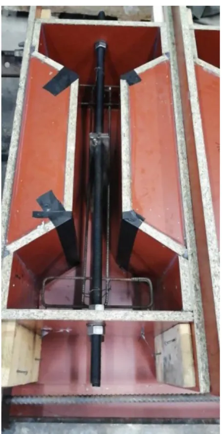
3.3 Specimen preparation ... 46
3.4 Test instrumentation and data acquisition ... 52
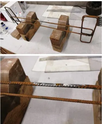
3.5 Trial test results ... 54
3.6 Conclusion ... 61
Chapter IV: Numerical modelling ... 63
4.1 FEM approach ... 63
XIV
4.3 Analysis ... 80
4.4 Mesh sensitivity ... 81
4.5 Verification of model ... 84
4.6 Results of finite element modelling ... 90
4.7 Conclusion ... 139
Chapter V: Conclusions ... 141
Chapter VI: Further recommendations ... 144
References ... 145
Annexes... 149
Annex A: External strengthening with SMA, material and testing ... 149
Annex B: Concrete compressive strength test for trial test ... 158
Annex C: Additional photos of the trial test ... 159
Annex D: Data sheet strain gauges [52] ... 163
Annex E: Data sheet epoxy adhesive [53] ... 164
XV
List of Figures
Figure 1: Critical zones on I-shape for debonding of FRP ... 4
Figure 2: Applying L-shaped prefab FRP-profiles [15] ... 8
Figure 3: Rolling the FRP surface in wet lay-up method [16] ... 8
Figure 4: Amounts of CFRP for T-beam tests [19] ... 10
Figure 5: Single-flanged specimens used in [21] ... 11
Figure 6: Anchorages for FRP in [11]: transverse strip (top), NSM bar (middle) and fan anchor (bottom) ... 13
Figure 7: Glued FRP-plates as anchorage [6] ... 14
Figure 8: FRP anchors for tests in [10] ... 15
Figure 9: Patch anchors on T-beams [26] ... 16
Figure 10: Anchorage types for tests in [19] ... 16
Figure 11: Single separate mechanical fasteners as anchorage [27] ... 17
Figure 12: Different NSM methods applied in [18] ... 17
Figure 13: NSM laminate bar on I-shaped girders [28] ... 18
Figure 14: Anchorage systems used in [4] ... 19
Figure 15: A π-anchor (top) [25], substrate strengthening (bottom left) [12] and hybrid anchor (bottom right) [25] ... 20
Figure 16: Bond-slip curve [8] ... 22
Figure 17: Bond-slip curves for FEA and 3 proposed models in [31] ... 23
Figure 18: Forces acting on an FRP-sheet [7] ... 24
Figure 19: Tri-linear bond-slip model for FRP-concrete interface [7] ... 24
Figure 20: Bond-stress distribution, 5 stages untill complete failure [7] ... 25
Figure 21: Metallic fastener anchorage with deformation part for ductility [7] ... 26
Figure 22: Different test methods for EB CFRP [30] ... 27
Figure 23: Improved double shear lap test [30] ... 28
Figure 24: Improved double shear test setup [8]: (a)= individual parts, (b)= assembled ... 29
Figure 25: Typical test setup for DIC [30] ... 30
Figure 26: DIC applied on T-beams with FRP [26] ... 30
Figure 27: DIC results for [26] with strain gauges ... 31
Figure 28: DIC test setup for T-beams in [33] ... 31
Figure 29: Influence of incremental distance on bond stress-slip curves [38] ... 37
Figure 30: Formwork dimensions [mm] ... 39
Figure 31: Stirrup lay-out and dimensions [mm] ... 40
Figure 32: Details of loading rebars and welded plates [mm] ... 41
Figure 33: Test setup [mm] ... 42
Figure 34: Test configurations with different anchors ... 43
Figure 35: Detail of a spike anchor... 44
Figure 36: Detail of mechanical anchor, sectional and front view ... 45
Figure 37: Detail of mechanical anchor, enlarged sectional view ... 45
Figure 38: Detail of patch anchor ... 45
Figure 39: Formwork with stirrup and loading rebars for trial test ... 46
XVI
Figure 41: Application of the strain gauge on the stirrup ... 50
Figure 42: Formwork with steel ... 51
Figure 43: Failure of trial specimen ... 55
Figure 44: Load-displacement behaviour for trial test ... 56
Figure 45: Load-strain behaviour for trial test ... 56
Figure 46: Trapezoidal force on FRP during trial test ... 57
Figure 47: New internal steel plate for final test specimens ... 60
Figure 48: Geometry and boundary conditions of the basic numerical model ... 64
Figure 49: First approach numerical model for I-shape ... 65
Figure 50: Geometry and boundary conditions of the basic I-shape ... 66
Figure 51: Model for direct approach, with adhesive layer ... 67
Figure 52: First way of modelling anchorage ... 68
Figure 53: Second way of modelling anchorage ... 69
Figure 54: FRP only over flange ... 70
Figure 55: Filling block with other properties ... 70
Figure 56: Adhesive layer and concrete filling block ... 71
Figure 57: FRP over flange and rounded corner to the top ... 71
Figure 58: Smaller concrete web ... 72
Figure 59: FRP longer at web (left) and at flange (right) ... 72
Figure 60: Changing opening angle of I-shape... 73
Figure 61: Numerical model of half of the I-shape ... 74
Figure 62: Concrete tensile curve by Hordijk [46] ... 76
Figure 63: Concrete compression curve by Thorenfeldt [46] ... 77
Figure 64: Bond-slip curve used in numerical model ... 79
Figure 65: Sketch of snap-through and snap-back behaviour [58]... 80
Figure 66: Chosen point for the arc-length control method in the nonlinear analysis (brown=FRP, grey=concrete) ... 81
Figure 67: Mesh used for rectangular specimen ... 83
Figure 68: Mesh used for I-shaped specimen ... 83
Figure 69: Mesh elements for numerical analysis (left=CQ16M, right=CT12M) [58] ... 84
Figure 70: Mesh element for interface [58] ... 84
Figure 71: Force-strain curves for numerical models in [46] ... 86
Figure 72: Load-displacement curve for basic rectangular case ... 87
Figure 73: Horizontal displacement for basic case ... 87
Figure 74: Comparison of strains for numerical model and results of [46] ... 88
Figure 75: Bond-slip curves for experimental tests (top left) [46], numerical model (top right) [46] and own numerical model (bottom) ... 89
Figure 76: Bond-slip curve when using different slip definition ... 90
Figure 77: Comparison slip at 42 mm from loaded end (left=[46],right=own model) ... 90
Figure 78: Load-displacement curves with different approaches ... 91
Figure 79: Concrete cracking for perfect bond approach ... 92
Figure 80: Strain distributions for direct approach ... 92
Figure 81: Total displacements at max load for partial supports ... 94
Figure 82: Load displacement curves for partial and full supports on concrete web ... 94
Figure 83: Load-displacement curves after changing bond length ... 95
XVII
Figure 85: Total displacements for basic I-shape (post-peak) ... 97
Figure 86: Points chosen to determine strain curve ... 98
Figure 87: Strain distributions along FRP length ... 99
Figure 88: Strains in concrete at ultimate load for I-shape ... 99
Figure 89: Bond stress-slip curve for I-shape ... 100
Figure 90: Load-displacement curves for different bond lengths along I-shape ... 101
Figure 91: Load-displacement curves for different opening angles... 101
Figure 92: Load-displacement curve with different load application point ... 102
Figure 93: Horizontal displacement when load applied above flange ... 104
Figure 94: Vertical displacements for load application above flange ... 105
Figure 95: Crack strains inside I-shape ... 106
Figure 96: Points chosen to determine strain curves ... 107
Figure 97: Strain distributions for load above flange ... 108
Figure 98: Bond stress-slip on I-shape when load applied above flange ... 108
Figure 99: Load-displacement curves for different models ... 109
Figure 100: Horizontal and vertical displacement at ultimate load for new model ... 110
Figure 101: Horizontal and vertical displacement close after ultimate load for new model ... 111
Figure 102: Bond stress-slip curves for new model ... 112
Figure 103: Load-displacement curves when concrete web is shortened ... 113
Figure 104: Load-displacement curves for different widths on rectangular block ... 113
Figure 105: Horizontal displacement for FRP 50 mm wide ... 115
Figure 106: Horizontal displacement for 75 mm wide ... 116
Figure 107: Zoom on post-peak behaviour for 75 mm FRP (horizontal displacement) ... 117
Figure 108: Bond stress-slip curves for 50 mm FRP ... 117
Figure 109: Strain distributions when FRP 75 mm wide on rectangular block ... 118
Figure 110: Load-slip curve at 42 mm for FRP 50 mm wide ... 118
Figure 111: Load-displacement curves for different widths on I-shape ... 119
Figure 112: Failure loads for different FRP widths ... 120
Figure 113: Load-displacement curves for different thicknesses on rectangular block ... 120
Figure 114: Strain distributions for FRP 1.05 mm thick ... 121
Figure 115: Bond stress-slip curves for FRP 0.7 mm thick ... 122
Figure 116: Slip at 42 mm for FRP 0.7 mm thick ... 122
Figure 117: Comparison FRP 75 mm wide against 1.05 mm thick ... 123
Figure 118: Comparison FRP 50 mm wide against 0.7 mm thick ... 124
Figure 119: Load-displacement curve with anchorage for basic rectangle ... 125
Figure 120: Load-displacement curve with anchorage for FRP 50 mm wide ... 126
Figure 121: Horizontal displacement for anchorage on FRP 50 mm wide ... 127
Figure 122: Bond stress-slip curve under anchorage ... 128
Figure 123: Load-displacement curve for straightened FRP... 129
Figure 124: Horizontal displacement when FRP only applied on flange ... 130
Figure 125: Vertical displacement when FRP only applied on flange ... 131
Figure 126: Crack strains when FRP only applied on flange ... 132
Figure 127: Crack strains when FRP applied over flange and rounded corner ... 133
Figure 128: Load-displacement curves with filling block ... 134
Figure 129: Horizontal displacement for FB with adhesive layer ... 136
XVIII Figure 131: Bond stress-slip curves for FB and adhesive layer ... 137 Figure 132: Horizontal displacement for cellular concrete FB ... 138
XIX
List of Tables
Table 1: Mechanical properties of CFRP [3] ... 2
Table 2: Comparison of different anchors out of [24] ... 20
Table 3: Comparison of different anchors out of [25] ... 21
Table 4: Overview of concrete models, interface approach and finite element software used for numerical modelling of FRP-concrete specimens found in literature ... 34
Table 5: Concrete composition ... 47
Table 6: Mechanical properties of steel ... 47
Table 7: Mechanical properties FRP as defined by the manufacturer [51] ... 47
Table 8: Contribution of FRP reinforcement (E=240 GPa) ... 61
Table 9: Material properties of concrete in numerical model ... 74
Table 10: Material properties of adhesive in numerical model ... 77
Table 11: Material properties of FRP in numerical model ... 78
Table 12: Different models used in the numerical model ... 79
Table 13: Mesh study for the rectangular specimen ... 82
Table 14: Mesh study for the I-shaped specimen ... 82
Table 15: Maximum loads for different modelling approaches ... 91
Table 16: Failure load and displacement for different load application point ... 102
Table 17: Maximum loads for different widths (rectangular block) ... 114
Table 18: Maximum load and displacement for different widths on I-shape ... 119
Table 19: Maximum loads and effective bond length for different FRP thicknesses ... 121
Table 20: Maximum loads with and without anchorage ... 126
XX
List of Abbreviations and Symbols
Ax surface of x
CCCM compression chord capacity model
CFRP carbon fibre reinforced polymer
DIC digital image correlation
DPM damage plasticity model
E modulus of elasticity / Young’s modulus
EB externally bonded
ε strain
F force
fs surface load
fc concrete compressive strength
fck characteristic concrete compressive strength
fcm mean concrete compressive strength
fctm mean tensile concrete strength
FACM fixed angle crack method
FB filling block
FEA finite element analysis
FEM finite element method
FRP fibre reinforced polymer
Gf fracture energy
GPa gigapascal (kN/mm²)
kN kilonewton
LVDT linear variable differential transformer
XXI
NSM near-surface mounted
ρ density
RACM rotating angle crack method
s slip
smax maximum slip
s𝜏max slip at maximum shear stress
SMA shape memory alloy
SME shape memory effect
𝜎 normal stress
𝜏 shear stress
𝜏max maximum shear stress
ν Poisson coefficient
Ф diameter
1
Preamble
At first, the focus of this master dissertation was to analyse the performance of CFRP and SMA for shear strengthening of I-shaped concrete cross-sections. A total of eight bond test configurations was designed: five with externally bonded CFRP and three with near surface mounted SMA reinforcement. A first change in the scope was done when the decision was made to only focus on CFRP-configurations and not anymore on SMA. The already studied part on SMA is thus moved as an Annex A: External strengthening with SMA, material and testing) at the end of this dissertation.
A trial test was performed to make sure that the test setup and the specimen design are working efficiently. Compression tests to confirm the concrete quality were performed as well. Later, eight specimens were cast and cured for one month. The experiments were scheduled from 31st March
to 3rd April, 2020. Unfortunately, because of the global outbreak of COVID-19 virus in 2020, the
Magnel Laboratory for concrete research at Ghent University was shut down on 18th March 2020
for an undefined period. Therefore, the planned tests could not be performed. As a consequence, the scope of this study had to be revised again, since the submission deadline was 31st May 2020.
The new scope focused on simulating the behaviour of the designed specimens numerically. For these numerical simulations, the finite element program DIANA 10.3 was used. At first, an FRP bond-slip experiment from the literature was calibrated using DIANA, to establish the finite element approach needed for further simulations of the I-section. Finally, conclusions based on numerical simulations are presented, to explain the behaviour of FRP shear strengthening configurations on I-shaped cross sections.
2
Chapter I: Introduction
It is generally known that concrete structures, such as buildings and bridges, degrade during their lifetime. This happens because of durability issues or because of other factors such as vandalism. Sometimes also a change in use or increase of the expected loads is the reason. In order to obtain the aimed service life of a structure, it is more feasible to execute strengthening techniques than to completely demolish and rebuild the structure. Strengthening of beams can be done in order to increase the flexural or shear strength, with the aim of performing repair works, strengthening the structure etc. Different possible strengthening techniques can be executed such as increasing the concrete cross-section by adding new concrete layers on the element, adding reinforcement inside the original cross-section or by using externally applied reinforcement. One of the most commonly used strengthening methods is the application of fibre reinforced polymers (FRP) as external reinforcement. FRP is usually bonded to the concrete member with a structural epoxy adhesive [1]. The FRP can be applied externally on the concrete, but another popular method is to use the near-surface-mounted (NSM) technique. In this technique, the FRP rebars/strips are applied inside a small groove cut in the concrete and covered by an epoxy layer. FRP rebars can also be used as internal reinforcement in concrete structural elements.
1.1 Fibre reinforced polymers
FRP consists of high-strength fibres embedded in a polymer matrix. These are based on different materials such as carbon, glass, aramid or basalt, but in general carbon fibres are the most used in construction industry [1]. They are preferred in construction industry since they possess excellent mechanical properties (Table 1). Moreover, they exhibit good resistance to creep and fatigue and they can handle chemical or moisture influences in a better way [2].
Table 1: Mechanical properties of CFRP [3]
Tensile strength [MPa] 600-3000 Modulus of elasticity [GPa] 80-500
Failure strain [%] 0.5-1.8 Density [kg/m³] ≈1550
3 CFRP consists of carbon fibres assembled in a polymer matrix. The polymer matrix is responsible for the bond between the carbon fibres and the transfer of forces between the individual fibres. Up to some extent the matrix also protects the fibres against environmental or mechanical damage. The carbon fibres give strength and stiffness to the material. Therefore, typically as much fibres as possible are present. In practice, about 60-70 % of the composite material consists of fibres. Depending on how the fibres are applied, different types are possible. First, all fibres can be placed in the same direction, i.e. the FRP is unidirectional and can only be used for strengthening in this direction. Other possibilities are bidirectional FRP, in which the fibres are assembled in orthogonal directions, and multidirectional FRP, in which short fibres are divided in the matrix [3].
CFRP strengthening has several advantages over steel, such as higher strength-to-weight ratio, higher ductility, higher flexibility, higher corrosion resistance, applicable on various cross-sectional shapes, fast and simple application, high tensile and fatigue strength, magnetically neutral and availability in different geometries and dimensions [4-6]. On the other hand FRP needs to be protected from UV-light, has low transverse strength, a limited failure strain, is a more expensive material than steel and can lead to brittle failure when debonding happens [3].
Different failure modes can be observed in FRP-strengthened concrete members. Concrete cover delamination or separation is the most common, but also anchor fracture, FRP rupture, plate end debonding, intermediate crack debonding, fibre slippage etc. can appear [7-10]. An FRP-concrete strengthened structure typically fails by debonding along the FRP-concrete interface, leading to a very low efficiency of the system [7]. Together with the early debonding, also a more brittle failure mode takes place. End peeling, concrete cover separation and mid-span debonding are commonly accompanying mechanisms. This happens mostly at the end of the FRP-sheet since high shear and normal stresses are present there. Concrete cover separation starts in a thin layer of concrete close to the surface, due to the fact that the tensile strength of concrete is usually lower than the ones of FRP and epoxy [11]. If the bond between the FRP and the concrete is stronger than the concrete itself, and the concrete strength is determined by the aggregates, the aggregate quality becomes the determining factor for the bond strength [8].
4
1.2 Problem statement
A lot of research about the use of FRP as a strengthening method for concrete structures has already been done in the past in order to achieve an easier and more economical process and to eliminate as much as possible the challenges when using FRP, such as FRP rupture and deterioration due to freeze-thaw or wet-dry cycles. However, there are still some specific aspects that need to be investigated further in detail[12].
One aspect that needs further attention is shear strengthening with FRP. Shear failure results in brittle collapse. Shear strengthening is, therefore, often required in order to have a safe design. In the case of I-shaped concrete cross-sections, some more specific problems considering the shear strengthening are imposed upon the debonding failure. The FRP-reinforcement works in tension which means the FRP wants to straighten. Since an I-shape introduces more corners along the cross-section and an opening compared to a rectangle shape is present, the FRP wants to debond in order to get the shortest length possible in tension, starting from the internal corner of the I-shape. The critical zone in which this debonding starts is indicated in Figure 1. The dotted line shows the most ideal situation for the FRP, in which it has the shortest length.
Figure 1: Critical zones on I-shape for debonding of FRP
Thus, a limitation on the use of FRP is that early debonding takes place when it is attached to concrete. In order to be able to use the full strength of the FRP, the FRP can be anchored on the concrete specimen.
5 In order to increase the efficiency of the system, an end anchorage is a suitable option to increase the ultimate load and avoid end peeling failure. Different anchorage types can be used such as a metallic fastener, transverse or U-wrapped FRP, an FRP-spike anchor, bolts, FRP rope anchors, NSM(B)-technique and gluing/bolting extra plates. Some more information on different anchorage types will be provided further in this master dissertation. In general, these anchors are the most efficient when the bonded length is smaller than the effective bond length, which can be calculated using design guidelines.
1.3 Objectives and methodology
In this thesis the bond behaviour of externally applied FRP on concrete I-sections is researched. The target of the carbon FRP is to increase the shear strength of these I-beams. The research is executed by numerical modelling of the I-shaped cross-section. The goal is to study the debonding behaviour of CFRP strengthened I-sections, using various CFRP arrangements with and without anchors. This is done in order to get some representative data to be able to make design rules and support widespread implementation of shear strengthening of I-shaped concrete members with FRP.
This study is performed by executing numerical modelling of a shear bond-slip test. Therefore a finite element analysis is executed using the software DIANA 10.3.
1.4 Overview
The general outline of the master thesis is as follows: - Chapter 1: Introduction
- Chapter 2: Literature study, in which the problem and methodology is understood by looking into similar studies that have been performed in literature
- Chapter 3: Experimental program, in which the specimen design, test setup and procedure are given and the obtained results are analysed - Chapter 4: Numerical modelling, in which a finite element approach is
cross-6 section, which is then further extended for I-shaped sections, and in which the numerical results are analysed
- Chapter 5: Conclusions, in which a short summary of the performed research together with the conclusions from the research are given - Chapter 6: Further recommendations, in which some recommendations
are given on the methods and aspects that need to be further investigated
7
Chapter II: Literature Review
In this chapter, an overview will be given on aspects found in literature concerning the problem statement as given in chapter one. First, different applying methods of the FRP are discussed, after which some specific shear strengthening aspects, different anchorage solutions and bond-slip behaviour are more specifically brought to light. Ay last, some research about numerical modelling of bond-slip tests is discussed.
2.1 Application methods
By using FRP, a reinforced concrete element is strengthened, which means the element will be able to take more forces from the point of applying on. However, the application of the FRP can be done in different methods with each of them having their (dis)advantages as will be explained in the following part.
In general, four application steps are followed to apply externally bonded FRP. First, the preceding repair of the concrete member to be strengthened is executed. Then, surface preparation is done, after which the FRP is applied. Lastly, some finishing operations and quality control is performed. The surface preparation means that the FRP is cleaned, cut to the right size and that the concrete surface is prepared by rounding the edges, roughening the surface (executed by grit blasting, sand coating, hydro-jetting, grinding..) and making it dust-free. The application of the FRP can be done in different ways: dry lay-up type, wet lay-up type and pre-cured FRP will be discussed here [3]. For the dry lay-up, the adhesive is first applied on the concrete and the FRP separately, after which the FRP is put on the concrete and some adhesive is squeezed out and needs to be removed [13]. For the wet application, the adhesive is first only applied to the concrete, then the FRP is put on the concrete and an overcoating of adhesive is used to impregnate the FRP. In both systems, the FRP needs to be treated with a roller to prevent debonding due to surface unevenness (Figure 3) and often multiple FRP layers are required [14]. For both techniques different epoxies need to be used: the wet technique requires a less viscous epoxy since the FRP should be impregnated with it. When prefabricated FRP-specimens are used, they can be applied using an adhesive but also application by using mechanical fasteners is possible [1]. For prefab applications, use can be made of FRP plates, which typically have a thickness of about 1 mm. For in-situ resin impregnated
8 systems, FRP sheets or strips are used. FRP sheets and strips typically have a thickness less than 0.5 mm and are less rigid compared to prefabricated FRP. More flexible forms can be executed, as U-wraps are e.g. only possible in the prefab method by using two L-shaped plates (Figure 2) [15]. In general, prefab FRP has a higher quality guarantee, but is less flexible in use.
Figure 2: Applying L-shaped prefab FRP-profiles [15]
Figure 3: Rolling the FRP surface in wet lay-up method [16]
An alternative is to use the near-surface-mounted technique to apply the FRP. In this technique, a groove is cut inside the concrete, then the groove is made dust-free and the epoxy resin is applied inside the groove after which the FRP-plate is put inside the groove and the excessive epoxy is removed [17]. In this technique the FRP is better protected against influences from outside (vandalism, fire…), but it is not always easy to make grooves inside the concrete element. The ultimate strain in which debonding will happen can be clearly higher when using NSM [2]. Usually
9 rather thin strips are used for this technique because in this way the contact surface is bigger which means smaller stresses will be developed and the normal stresses act mainly in the thick lateral layer of concrete. As a result, less chance on splitting of the concrete has been obtained. Advantages are: no surface preparation on the concrete is needed, less risk of debonding, protected from vandalism, better durability, cracks in the concrete can be seen visually and it performs better for strengthening negative moments, since the FRP is applied closer to the neutral fibre (inside the concrete instead of outwards) [18]. The structure is less affected aesthetically as well. Especially in flexural strengthening this method is advantageous against externally bonding because NSM bars can be easily anchored in adjacent members to transfer the moment. Although the results with NSM are better than with EB, still the same failure modes are present, mostly interfacial debonding between the bar and the epoxy or concrete cover separation. A large number of parameters can influence the failure (mechanical properties of the materials, surface properties of the FRP and the groove, tensile strength of the epoxy and the concrete, the dimensions of the groove…) and research is still to be recommended to be able to estimate the separate influences of these parameters.
2.2 Shear strengthening of beams
While for flexural strengthening the FRP is applied on the upper and lower side of the specimen as much as possible in order to eliminate the working moment on the element, shear strengthening can be applied all around the specimen.
Different parameters play a role in the performance of shear strengthening of a reinforced concrete beam [4, 18, 19]. Research can be found on different types of beams, literature about I-beams and T-beams and different anchorage systems in general has been chosen for analysis given their relevance for this thesis.
In general, beams strengthened with CFRP are observed to have a better ductile behaviour compared to unstrengthened beams. Furthermore, not only the ultimate shear force is increased, but also the cracking shear force is enlarged and the cracking widths are reduced [19]. Using FRP to strengthen the concrete beam is also not as effective for a prestressed concrete beam compared to a reinforced concrete beam [4].
10 A first issue in using CFRP as shear strengthening is whether the CFRP has to be applied continuous along a beam or whether it can be placed on certain zones only (Figure 4) [19]. The CFRP-reinforcement (0.17mm thick) was applied in U-shape configuration and four different amounts of CFRP have been used, including no CFRP and the three types shown below.
Figure 4: Amounts of CFRP for T-beam tests [19]
Out of the different tests performed, following observations were given:
-the FRP strengthening system modifies the strut orientation (the cracks appear under another angle)
-type 3 (continuous FRP) does not give better results than type 2, where FRP is only present following a certain pattern, however, type 2 does give better results than type 1
The orientation of the FRP reinforcement is influencing the shear strengthening behaviour as well [4, 18]. Several experimental tests have been executed with regard to this subject, mostly comparing an angle of 90°, at which the FRP is applied straight at the side of the concrete member, with an angle of 45°, where the FRP is applied at an angle compared to the horizontal axis of the beam. It has been shown that applying the FRP at an angle of 45° has better effectiveness than applying the FRP at an angle of 90° due to the fact that shear cracks appear at an angle of about 45° in concrete structures.
The effectiveness of using CFRP as external reinforcement against steel plates has also been tested [18]. It was shown that CFRP performs better than steel as long as the danger of debonding can be eliminated good enough.
For the choice of the adhesive which can be used, research showed that an adhesive with a lower Young’s modulus has a better bond capacity, but a lower tensile strength compared to an adhesive with a higher modulus [20]. However, it is also reported in literature that failure of the adhesive only rarely happens.
Another observation found in literature [11] is that by increasing the width of the used CFRP-sheet, the increase in ultimate load follows about the same trend. However, applying separate small sheets that have the same width as one larger sheet is disadvantageous.
11 In the PhD thesis of Hutchinson [21], tests on rectangular and single-flanged specimens were performed. For the single-flanged specimens (Figure 5), a crack angle of 0° and of 30° was applied. The starting point of the crack was on the internal corner of the flange to web or 50 mm from this corner along the web. Sometimes steel crossing the crack was used and different sheet peeling control methods in the corner were used. For the rectangular specimens two surface preparation techniques, grinding and hydro-blasting, were investigated.
Figure 5: Single-flanged specimens used in [21]
The test results learn that hydro-blasting is a better surface preparation technique then grinding and that clamping is the best method to handle with sheet peeling. Applying a crack angle of 30° is better than an angle of 0°, the cracking start point is better along the web and not in the corner and steel crossing the crack only has a small influence on these cracks. Also, it was made clear that in every case the I-shape had a lower failure load compared to the rectangular specimen, since debonding took place earlier. Also in [4] it is confirmed that the effectiveness of the CFRP varies with the shape of the cross-section and with the reinforcing scheme. Furthermore, it is pointed out that web crushing failure mode is dangerous for thin webbed sections, in this case reduction of the failure load is observed.
By performing different types of tests, it is also shown that there exists an active bonding zone along which the interfacial load is transferred between the applied FRP and the concrete. When the FRP is bonded along a larger length on the concrete, the failure load will stay more or less constant. The bond length at which this phenomenon happens is called the effective bond length. In some investigations it is also stated that the failure load still had a slight increase when the bond
12 length becomes larger then the effective bond length. However, the increase was only very small and was rather insignificant on the total failure load [22]. It was also proved that when the concrete-FRP bonded joint is subjected to water immersion, the effective bond length decreased and the failure load reduced [23].
As last issue, research has been done to the performance of CFRP under high service temperatures [2]. It appeared that higher failure loads can be achieved under higher temperatures until the transition temperature of the adhesive is reached, which is about 65 °C. When the temperature is raised above 65 °C, the adhesive gets softened and the strengthening becomes less effective.
2.3 Anchorage solutions
A possible solution for the early debonding failures which can be observed when applying externally bonded CFRP is to anchor the CFRP-sheet inside the concrete specimen. A whole number of anchorages has already been proposed by different researchers. A non-exhaustive list of possibilities is given here: a metallic fastener, transverse or U-wrapped FRP, an FRP-anchor (=rope anchor, spike anchor), bolts, FRP rope anchors, NSM(B)-technique, gluing/bolting extra plates, a patch anchor, hybrid bonding system, mechanical substrate strengthening, embedment in flange,… [12, 24, 25]. Some more info about the different anchorage systems is given in the following part and, if possible, a comparison of the effectiveness is made.
A comparison in performance between a CFRP transverse strip, a NSM CFRP bar and a CFRP fan (Figure 6) is done in [11]. A CFRP fan consists out of a carbon tow which is forced through an epoxy-filled hole and spread out at both sides, where one of these sides joins the CFRP-sheet. In general, the CFRP fan gave the best results, followed by the CFRP NSM bar. With the CFRP transverse strip the lowest failure loads were reached. However, the transverse strip showed to be the most reliable and easy option, since it is less influenced by detailing and the application procedure. Another advantage of the transverse strip is that more ductile behaviour was present. With the NSM bar and the fan, the strains suddenly increased quickly when close to the failure load (>90%). On the other hand, a lot of space is needed to apply the transverse strip. When the width of the concrete element is close to the width of the CFRP-sheet, then no space is available anymore to apply a transverse strip. An optimal configuration was achieved when the length of the transverse strip was equal to three times the width of the applied sheet.
13
Figure 6: Anchorages for FRP in [11]: transverse strip (top), NSM bar (middle) and fan anchor (bottom)
Some more tests with NSM anchorages were performed in [6]. T-beam sections were used and the anchorage was applied on the inner corner between the web and the flange, where the debonding is expected to happen first. Next to some NSM anchorages also bolted/glued steel and glued CFRP plates (Figure 7) were investigated. The FRP-sheets were stopped at the corner or they were elongated along the web.
14
Figure 7: Glued FRP-plates as anchorage [6]
As it turned out, elongating the sheet along the flange or stopping the FRP-sheet at the inner corner does not have great influence on the results. When elongated along the flange, premature debonding can occur, since gluing at these L-shapes is rather uncertain. Since debonding occurred in the corner, the full capacity of the FRP strengthening was not used. Therefore, the effectiveness of it should still be researched. It was evidenced that with the different anchorage systems the failure load can be more than doubled, so the correct detailing is very important. Bolting the steel plates and filling the NSM groove with an extra FRP-bar gives local high stresses and can thus lead to local failure. The NSM-technique gives highly variating results, so detailing of the procedure is proved to be important and gluing steel/FRP plates along the web is a more reliable and easy solution to perform anchorage and increase the failure load.
In [10] the performance of FRP-anchors was investigated. The anchors were made by rolling up the FRP fibres and anchoring these ropes inside the concrete specimen. Different dowel angles were tested (Figure 8), just as different application techniques, different embedment depths and different surface preparation techniques (smoothing of hole edge).
15
Figure 8: FRP anchors for tests in [10]
The precured installation technique consisted out of impregnating and rolling the FRP anchor at least 24 hours before the application while with the wet installation technique the FRP was applied immediately after impregnation. No significant differences in the test results between both techniques was found. The test results showed a linear proportional increase with increase of embedment depth. Three different dowel angles were used, namely 90°, 120° and 135°. Between 90° and 120° no differences were present, but the angle of 135° showed clearly better behaviour: fibre rupture of the free end was reached and the failure loads were higher (+20%). The smoothening of the hole edges was done with a grinding machine or a customized drill bit. The customized drill bit showed similar results to the non-smoothened cases, but the grinding showed higher failure loads (+25%).
In [26], patch anchors were used to anchor U-wrapped FRP-laminates along post-tensioned T-beams (Figure 9). The patch anchors consisted out of a transverse bi-directional FRP-sheet, after which the FRP-laminates were applied and on top of this again a bi-directional FRP-sheet was applied in the transverse direction. While the strengthened beam with FRP but no anchors reached an increase of 20-30% in shear failure force, the specimens with patch anchors reached a significant increase of about 60%. The failure mode, however, was still debonding of the FRP, which started under the patch anchor.
16
Figure 9: Patch anchors on T-beams [26]
Mechanical anchorages at the top of the concrete web can be used as well. Two types of mechanical anchorages were compared in [19] (Figure 10). In type A, a multidirectional CFRP laminate (3mm thick) was glued under the bolts (Ф10mm) to avoid damage in the externally applied reinforcement and in between this laminate and the bolts a steel plate (4mm thick) was placed to avoid stress concentrations. In anchorage type B, the CFRP strips were wrapped around a steel plate (4mm thick) which was bonded parallel at the beam axis under the flange, and bolts (Ф10mm) were placed in between the CFRP strips.
Figure 10: Anchorage types for tests in [19]
By using these anchorage types the contribution of the CFRP in the ultimate shear load gets significantly higher in relation to the steel reinforcement which was present inside the tested beams. However the analysis of the FRP shear contribution to the total shear force resistance can’t be researched in a good way because of the complexity of the shear behaviour and failure modes [4].
17 Between the two tested types it appeared that anchorage type A performed better under low amount of steel and/or CFRP reinforcement, while anchorage B performed better under higher amounts.
When separate mechanical fasteners (Figure 11) were used, it was shown that the slip between the FRP and the concrete can get reduced if the different fasteners are put close against each other [27]. However, it is still advised to divide the fasteners over the complete bonded length of the FRP, since this increased the ductility and enhanced the fastening of the FRP to the concrete.
Figure 11: Single separate mechanical fasteners as anchorage [27]
Anchoring CFRP-bars inside the concrete flange in a T-shape (Figure 12) was investigated in [18]. The research showed that extending the reinforcement in the flange strengthened the structure, but the effect was rather limited. Moreover, it is limited in practical use, since the connection between the web and flange has to be disrupted.
Figure 12: Different NSM methods applied in [18]
In [28], test were performed on bridge I-shaped girders which have been in service for 42 years. FRP was applied and anchored with a horizontal strip and with a laminate as NSM-bar (Figure 13). The results showed, however, that using this laminate as NSM-bar did not have the desired effect, since the stresses were built up at the side of the groove and tensile cracks elongated through the
18 bottom web. The use of a horizontal strip, on the contrary, performed very well and increased the failure load about 19% compared to unanchored specimens.
Figure 13: NSM laminate bar on I-shaped girders [28]
In [4], 16 prestressed I-shaped concrete beam tests were performed. Different cross-sections, strengthening schemes, anchorage systems and transverse steel reinforcement ratio were investigated. Four cross-section types were used, in which the design of the cross-section was each time improved to give more stiffness to the flange. Also four different anchorage systems were used: continuous mechanical anchorage (CMA), discontinuous mechanical anchorage (DMA), sandwich panel discontinuous anchorage (SDMA) and horizontal CFRP strips (HS) (Figure 14). For the CMA, a continuous steel plate is put on top of the FRP and anchored with bolts. For the DMA, little steel plates were used and fixed with bolts. For the SDMA two different steel plates were fixed on top of the FRP and the FRP was turned in between these plates. The CFRP reinforcement was applied on an angle of 90° or 45°. In one beam pre-existing cracks were made in order to investigate the behaviour after little damage.
19
Figure 14: Anchorage systems used in [4]
After performing the tests, several aspects were distinguished. First of all, the effectiveness of the external CFRP strengthening is strongly influenced by the failure mode. Secondly, the CMA anchorage system performed poorly, the DMA system performed better but still didn’t prevent debonding of the CFRP, the HS system had results somewhere in between the CMA and the DMA, but the SDMA anchorage performed best and led to FRP rupture instead of debonding.
A comparison of some more anchorage types was performed in [12, 24, 25]. In order to do the comparison, results were taken out of different other research reports and the strain reached in the
![Figure 17: Bond-slip curves for FEA and 3 proposed models in [31]](https://thumb-eu.123doks.com/thumbv2/5doknet/3278444.21533/44.892.254.646.208.479/figure-bond-slip-curves-fea-proposed-models.webp)
![Figure 26: DIC applied on T-beams with FRP [26]](https://thumb-eu.123doks.com/thumbv2/5doknet/3278444.21533/51.892.263.637.129.445/figure-dic-applied-t-beams-frp.webp)