1 van 6 21-3-2014
Natural air supply
Kennisbank Bouwfysica
Auteurs: dr. Edward Prendergast (moBius consult), dr.ir. Peter van den Engel
1 Introduction
Until the middle of the 2000th century, natural ventilation was the only ventilation principal used in buildings. Most often there were no special measures to ensure ventilation other than windows that can be opened. Complete natural ventilation of housing remained the norm until the 1980’s. From the 1960’s ventilation grids were installed to make ventilation possible without opening a window. From the 1980 the combination of natural inlet with a mechanical exhaust in housing started to be used more and more. This principle is still used in many new housing projects nowadays. In utility buildings although still regularly applied, natural ventilation is no longer the norm.
From the perspective of indoor climate and natural, ecological or biological construction natural ventilation is preferred over mechanical systems. From the perspective of energy saving, usually mechanical ventilation is preferred. It is important to note that both indoor a good climate and energy saving can be realised with both natural ventilation as mechanical ventilation. In all cases the quality of the design and the construction is essential in realising the objective.
It is important to note that nowadays there are minimum requirements of air supply to buildings. These also hold when natural ventilation is applied. Standardised calculations methods (using supplier data) are used to calculate the required area of ventilation grids necessary in new buildings. This can have a significant impact on the outlay of the façade of a building.
As is common in the building sector in the Netherlands, in this module the term natural ventilation is used when the inlet of air is directly from the outside. Whether or not there is a mechanical system for exhaust, is not relevant for this aspect.
2 Ventilation principles
In order to ensure good air quality, a separate air inlet and outlet are necessary. Nowadays the outlet usually has a mechanical exhaust, ensuring negative pressure and a continuous flow of air. When natural exhaust is used, the in- and outlet should be realised in opposing facades and ample overflow provisions have to be installed. When there is some wind, a natural pressure difference between the two facades will occur.
One of the advantages of natural ventilation is that there is little chance of short-circuiting between inlet and outlet. Because in and outlet are on different sides of the room a good ventilation efficiency is achieved.
2 van 6 21-3-2014 Figure 1: Diagram of an air inlet and outlet system in a room
3 Air inlets en overflow
Many different types of natural air inlets are available. There are very simple systems which are basically not much more than a hole in the wall. These systems are sometimes applied in refurbishment projects.
The most common types are the ventilation grids which are (usually) located over windows. As already stated, the area of ventilation grid that has to be applied has to be calculated using data from the supplier about the flow of air through the grid. There are many different kinds of
ventilation grids available. Amongst others the following are most commonly applied: Standard ventilation grid
No special features other than that it can be opened and closed by the user. Pressure regulated ventilation grid
Standard grids will allow more air through when (wind)pressure increases. Pressure regulated ventilation grids always ensure a maximum air flow. This reduces energy losses and reduces draught risk.
Noise insulating ventilation grid
These are applied when a façade has a high noise level. The noise is highly reduced through the grid. To achieve this noise reduction, the grid is relatively deep. The architectural impact of such grids, on the inside or on the outside of the façade is big. Demand regulated (electronic) ventilation grids
The aperture of these grids can be electronically manipulated, reducing or increasing the airflow. Usually these are applied in combination with a mechanical controllable variable outlet. The flow is usually controlled by CO2-measurement or a timer.
A combination of the above types are also readily available.
To ensure ventilation flow to rooms not situated on a façade, the outlet has to be situated in such a room. Besides this, overflow provisions have to be installed. Most commonly this is a slit under the door of 20 mm or more. To allow airflow in combination with noise insulation, special overflow grids are available, which can be installed in the door or in a wall.
4 Draught
Draught is a mayor risk when using natural ventilation. The feeling of draught is influenced by many parameters. Usually draught is produced by high air velocity combined with high air
inlet outlet
3 van 6 21-3-2014 turbulence and a moderate or low operative temperature. The lower the temperature, the easier draught will occur. To evaluate this risk, a prediction of local thermal discomfort can be calculated with the Draught Rating approach. The amount of people that will be dissatisfied with thermal comfort can be predicted. In the NEN-EN-ISO 7730 there are three categories:
A. maximal 10 % dissatisfied users B. maximal 20% dissatisfied users C. maximal 30% dissatisfied users
Draught ratings are usually measured at 0.1 m (near the feet) and 1.1 m (neck height of a sitting person) above the floor.
The risk of draught depends on the amount of fresh air that is supplied. The amount of fresh air is proportional to the occupancy of a room. In houses, the occupancy is usually low, for instance 1 person per 20 m2. In schools, the occupancy is high, for instance 1 person per 2 m2.
table 3. Some typical occupancy levels related to different functions.
Function House Office School Theatre, cafe
m2 per
person
15 – 35 6.5 – 20 1.3 – 4 0.5 – 3
Draught prevention
In order to prevent draught following rules of thumb can be followed: - limit the amount of fresh supplied air to 10 l/s per m air inlet
- choose the position of the air inlet as high as possible, but at least 1.80 m above floor level
- when a radiator or convector is applied under a window, it is easier to compensate downdraught from cold air supply
- when more than 10 – 15 l/s m has to be supplied, special measures are necessary Technical solutions to prevent draught with high air flows
There are several options to prevent draught when the air flow is more than 15 l/s: - supply the at a positions where there are no occupants
- supply the air above a false ceiling
4 van 6 21-3-2014 4.1 False ceiling
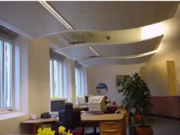
In figure three an illustration is shown with natural ventilation via a false ceiling.
Figure 3: Air supply above a false ceiling in order to prevent draught. The position of the outlet needs attention as well in order to prevent short-circuiting of air flows.
In this solution, it is important to ensure that no short-cut between inlet in the room and outlet exists and that there is a good ventilation efficiency of the room.
Figure 4: Air supply above a climate ceiling in order to prevent draught.
Figure 4 shows a specially designed climate ceiling which is used to shield the user from cold air. However, when the air velocity is too low draught is still possible, so enough pressure difference over the façade (for instance 10 Pa) should be maintained.
4.2 Coanda-effect
best position exhaust: promote circulation prevent short-circuiting prevent draught
5 van 6 21-3-2014 Draught risk can be diminished by making use of the so-called coanda-effect. This is the
phenomenon that an airflow along a surface tends to stick to this surface. It is illustrated in the figure below.1
Figure 5: Illustration of the coanda-effect
Below there are several examples how this effect can be used in buildings to reduce draft.
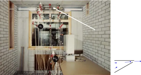
Figure 6: Option of air supply without draught (DR < 20%, according to the NEN-EN ISO 7730) with an air inlet just beneath the ceiling (in the picture the white arrow). With an air inlet element length = 1 m, height = 20 mm > 45 l/s, 0oC per m can be supplied. To have a low air resistance it is recommended to make use of a venturi shape
of the air inlet. The picture is from a test chamber at the Delft University of Technology (4), with measurement equipment for velocity and turbulence, temperature, etc. The air supply makes use of the venturi principle (shown at the right side of the picture, not shown in the picture itself). The system has been supplied in several schools.2
1When the turbulence near the inlet is very high, due to the small size of the inlet, cold air will be mixed up with the surrounding
warm air very quickly. This is an additional positive effect as well.
2Tochtvrije natuurlijke ventilatie in Basisschool De Schakel. Bouwwereld 6, 22 mei 2012 P = low
6 van 6 21-3-2014
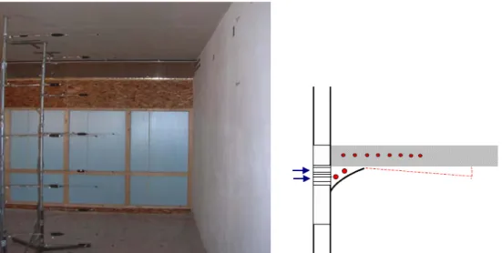
Figure 7: For a school this system has been adapted. Two air inlets are placed above each other (the silverish horizontal lines high in the back wall) and a spoiler has been added to it (shown in drawing). The air is preheated till 0 oC or more by two pipes. This system will be combined with thermally activated concrete floor above. The
picture is from a test chamber in a laboratory of Cauberg-Huijgen Consulting Engineers, Zwolle. To prevent frost of the pipes in case of system failures, a water-glycol mixture is used as a heating medium. The system was applied in the ROC of Twente. During the night, etceterfa, the inlet is closed off automatically in order to save energy and to improve temperature control.
Figure 8: Example of an air supply-system in the Amolf research-building in Amsterdam (Dick van Gameren/De Architectengroep) with little draught risk. The air supply is protected and hidden by a concrete façade-element and is equipped with a self regulating valve as well. A convector provides better local comfort and is another means to prevent downdraught. The system can be combined with thermally activated building elements.