CYCLODEXTRIN METAL-ORGANIC FRAMEWORKS
FOR BIOLOGICAL APPLICATIONS
Ine Vander Haegen
A Master dissertation for the study program Master in Pharmaceutical Care
CYCLODEXTRIN METAL-ORGANIC FRAMEWORKS
FOR BIOLOGICAL APPLICATIONS
Ine Vander Haegen
A Master dissertation for the study program Master in Pharmaceutical Care
Academic year: 2019 – 2020
Master dissertation submitted to the faculty of Pharmaceutical Sciences, performed in collaboration with the research group XStruct – Bio-Inorganic Chemistry
Promotor: Prof. dr. K. Van Hecke
Commissioners: Prof. dr. Serge Van Calenbergh and Prof. dr. Bart De Spiegeleer
The information, conclusions and points of view in this master dissertation are those of the author and do not necessarily represent the opinion of the promoter or his research group.
Deze pagina is niet beschikbaar omdat ze persoonsgegevens bevat.
Universiteitsbibliotheek Gent, 2021.
This page is not available because it contains personal information.
Ghent University, Library, 2021.
Abstract
Cyclodextrin metal-organic frameworks (CD-MOFs) have already been used in several applications because of their unique properties, as they contain the cavity structures of !-cyclodextrins and the cage structures of metal-organic frameworks. An example of such an application is drug delivery, where CD-MOFs are especially used to enhance the bioavailability and water solubility of active pharmaceutical substances. The ultimate goal of this thesis was the synthesis of core-shell nanoparticles of !-CD-MOFs with rhodamine B (RhB) and fluorescein (FL) incorporated into the core or shell. Rhodamine B is an amphoteric, xanthene dye and an organic chloride salt, which is used as a fluorescent dye, while fluorescein is an organic compound, which is widely used as a synthetic coloring agent. The purpose of making these core-shell materials at the nanoscale was to use them in biological applications such as luminescence temperature sensing in cells, with the example of tumor cells. Because of the faster metabolic rate of tumor cells, they produce more heat than normal cells, which can cause temperature changes. It is suggested that there is a correlation between the degree of malignancy of the tumor and the amount of temperature rise and more specifically, the hotter the tumor, the more virulent its biological nature. This indicates that the use of suitable temperature measuring devices is of great value in early cancer diagnosis. Example of such temperature measuring devices are so-called ratiometric thermometers, which are based on the intensity ratio of two transitions. Currently, there’s only a few reports about ratiometric thermometers containing organic compounds, such as dyes like rhodamine 110 and rhodamine B. Here, we proposed to develop a ratiometric thermometer, based on rhodamine B and fluorescein, incorporated in !-CD-MOFs. As such, !-CD-MOF crystals, !-CD-MOF⊃RhB/FL crystals and !-CD-MOF core-shell crystals were synthesized using specific vapor diffusion methods. Single-crystal X-ray diffraction analysis was performed on a !-CD-MOF crystal to elucidate its molecular structure, while the !-CD-MOF⊃RhB/FL crystals were analyzed using powder X-ray diffraction (PXRD) techniques. The results of the single-crystal X-ray diffraction analysis showed that the compound crystallized in the monoclinic space group C2 with chemical formula C288H336K9O240. From the specific unit cell parameters, it already became clear that this crystal had not been reported in literature yet and thus appeared to be a new polymorph. However, the PXRD results showed a match between the simulated diffractogram, based on a previously reported structure of a !-CD-MOF in the cubic space group I432, and the experimental diffractograms, which indicated that the bulk material of the CD-MOF⊃RhB/FL crystals corresponded to the latter structure, rather than the new polymorph.
Samenvatting
Cyclodextrine metaal-organische roosters (CD-MOFs) worden reeds gebruikt in verschillende toepassingen omwille van hun unieke eigenschappen, met name omdat ze de caviteitsstructuur van γ-cyclodextrines en de roosterstructuur van metaal-organische roosters bevatten. Een voorbeeld van dergelijke toepassing is geneesmiddelafgifte, waarbij CD-MOFs voornamelijk gebruikt worden voor het verbeteren van de biologische beschikbaarheid en de wateroplosbaarheid van actieve farmaceutische substanties. Het ultieme doel van deze thesis was de synthese van core-shell nanopartikels van γ-CD-MOF's met rhodamine B (RhB) en fluoresceïne (FL) in de core
of shell geïncorporeerd. Rhodamine B is een amfotere kleurstof, op basis van xantheen, en een organisch chloridezout, dat wordt gebruikt als fluorescerende kleurstof, terwijl fluoresceïne een organische verbinding is die op grote schaal wordt gebruikt als een synthetische kleurstof. Het maken van deze core-shell nanomaterialen had als doel deze te gebruiken in biologische toepassingen zoals het waarnemen van temperatuur op basis van luminescentie in cellen zoals bijvoorbeeld tumorcellen. Door de hogere metabole snelheid van tumorcellen produceren deze meer warmte dan normale cellen, wat temperatuursveranderingen kan veroorzaken. Er wordt gesuggereerd dat er een correlatie bestaat tussen de mate van kwaadaardigheid van de tumor en de mate van temperatuurstijging en meer specifiek, hoe hoger de temperatuur van de tumor, hoe virulenter de biologische aard ervan. Dit toont aan dat het gebruik van geschikte meetapparatuur voor de temperatuur van grote waarde is bij het stellen van een vroege diagnose van kanker. Voorbeelden van dergelijke meetapparaten zijn ratiometrische thermometers die gebaseerd zijn op de intensiteitsverhouding van twee transities. Er zijn momenteel slechts enkele gerapporteerde ratiometrische thermometers gebaseerd op organische verbindingen, zoals kleurstoffen met als voorbeeld rhodamine 110 en rhodamine B. Hier beogen we om een ratiometrische thermometer te ontwerpen, gebaseerd op rhodamine B en fluoresceïne, geïncorporeerd in MOFs. Aldus werden MOF-kristallen, MOF⊃RhB/FL-kristallen en γ-CD-MOF-core-shell kristallen gesynthetiseerd met behulp van specifieke dampdiffusiemethoden. Enkelkristal X-stralenanalyse werd uitgevoerd op een γ-CD-MOF-kristal om vervolgens de moleculaire structuur op te helderen, terwijl de γ-CD-MOF⊃RhB/FL-kristallen werden geanalyseerd met behulp van poederdiffractietechnieken (PXRD). De resultaten van de enkelkristal X-stralendiffractie analyse toonden aan dat de γ-CD-MOF uitkristalliseert in de monokliene ruimtegroep C2 met chemische formule C288H336K9O240. Uit de eenheidscel constanten werd duidelijk dat dit kristal nog niet beschreven werd in de literatuur en dus een nieuw polymorf bleek te zijn. De PXRD resultaten toonden tevens de gelijkenis aan tussen de gesimuleerde – op basis van de eerder gerapporteerde !-CD-MOF in de kubische ruimtegroep I432 – en de experimentele diffractogrammen, wat aantoont dat de structuur van het
bulkmateriaal van de CD-MOF⊃RhB/FL kristallen eerder overeenkomt met deze laatste structuur in plaats van het nieuwe polymorf.
Acknowledgements
Writing this thesis, which was a challenge for me, could not have been made possible without some people. I would like to express my gratitude to these people who made it possible to bring this thesis to a successful conclusion.
My greatest appreciation to my promoter Prof. dr. Van Hecke, whom I could always contact with questions, for reading my thesis over and over and always giving constructive feedback. I feel honored that I was given the opportunity to do research on this rather new subject.
Thank you to the research group XStruct – Bio-Inorganic Chemistry, in special Min Peng, for the excellent guidance in the lab. I really enjoyed working in the lab and experiencing the progress of this research.
I also want to thank Prof. dr. Kaczmarek for her help in writing the luminescence and temperature sensor section. Unfortunately, finally it wasn't possible to do research in her lab.
Special thanks to my parents, for always supporting me, giving me all these chances and always believing in me. You mean the world to me.
Thanks to all of you, Ine Vander Haegen
Index 1. INTRODUCTION ... 1 1.1. CYCLODEXTRINS ... 1 1.1.1. Historical background ... 1 1.1.2. Structure ... 1 1.1.3. Synthesis ... 2 1.1.4. Properties of cyclodextrins ... 2 1.1.5. Applications ... 3 1.2. METAL-ORGANIC FRAMEWORKS ... 3
1.3. CYCLODEXTRIN METAL-ORGANIC FRAMEWORKS ... 4
1.3.1. Structure ... 4 1.3.2. Synthesis ... 5 1.3.3. Applications ... 6 1.3.4. Characterization ... 10 1.3.5. CD-MOF overview ... 10 1.4. CORE-SHELL NANOPARTICLES ... 16 1.4.1. Structure ... 16 1.4.2. Properties ... 16 1.4.3. Applications ... 17 1.5. X-RAY DIFFRACTION ... 17 1.5.1. Historical background ... 17 1.5.2. Bragg’s law ... 18 1.5.3. Reciprocal space ... 19 1.5.4. Ewald’s sphere ... 19
1.5.5. Powder X-ray diffraction ... 20
1.5.6. Single-crystal X-ray diffraction ... 21
1.6. LUMINESCENCE ... 25
1.6.1. Temperature dependent luminescence ... 25
1.6.2. Luminescence nanothermometry ... 25
1.6.3. Dyes ... 29
2. OBJECTIVES ... 31
3. MATERIALS AND METHODS ... 32
3.1. SYNTHESIS OF !-CD-MOF CRYSTALS ... 32
3.2. SYNTHESIS OF CD-MOF⊃RhB/FL CRYSTALS ... 33
3.3. SYNTHESIS OF CORE-SHELL STRUCTURED CD-MOF CRYSTALS ... 36
4.1. STRUCTURE DETERMINATION OF !-CD-MOF CRYSTALS BY SINGLE-CRYSTAL X-RAY ANALYSIS ... 38
4.2. STRUCTURE DETERMINATION OF CD-MOF⊃RhB/FL CRYSTALS BY POWDER X-RAY ANALYSIS ... 38
4.3. TEMPERATURE SENSING ... 40
5. DISCUSSION ... 44
5.1. STRUCTURE DETERMINATION OF !-CD-MOF CRYSTALS BY SINGLE-CRYSTAL X-RAY ANALYSIS ... 44
5.2. STRUCTURE DETERMINATION OF CD-MOF⊃RhB/FL CRYSTALS BY POWDER X-RAY ANALYSIS ... 45
5.3. TEMPERATURE SENSING ... 46
6. CONCLUSION ... 47
7. BIBLIOGRAPHY ... 48
List of used abbreviations Å: Ångström (10-10 meter) %w/v: weight/volume percentage °C: degrees Celsius 3D: three-dimensional CCD: charge-coupled device
CCDC: Cambridge Crystallographic Data Center CD-MOF: cyclodextrin metal-organic framework CD: cyclodextrin
CGTase: cyclodextrin glycosyltransferase CoQ10: coenzyme Q10
COX: cyclo-oxygenase CsOH: cesium hydroxide FL: fluorescein
IUPAC: International Union of Pure and Applied Chemistry K: Kelvin
KCl: potassium chloride KOH: potassium hydroxide LiOH: lithium hydroxide mg: milligram
ml: milliliter
MOF: metal-organic framework nm: nanometer
ppm: parts per million PXRD: powder X-ray diffraction RbOH: rubidiumhydroxide RhB: Rhodamine B Sa: absolute sensitivity Sr: relative sensitivity μm: micrometer
Preamble
First, the synthesis of CD-MOF crystals was performed, with and without dyes incorporated. The next goal was to synthesize core-shell crystals, after which these crystals would be prepared at the nanoscale. These core-shell nanoparticles could be used in biological applications such as temperature sensing using dyes with temperature dependent luminescence. This temperature dependent luminescence could be determined via luminescence studies. Before the SARS-CoV-2 crisis, CD-MOF crystals with and without incorporated dyes, respectively, were synthesized. On a CD-MOF crystal, single-crystal X-ray diffraction analysis was performed to elucidate its molecular structure, while the CD-MOF crystals with dyes incorporated were analyzed by powder X-ray diffraction techniques. At the moment the SARS-CoV-2 crisis started, we had been working on the optimization of the synthesis of CD-MOF⊃RhB/FL crystals. This optimization was required to use the crystals in luminescence studies that would have taken place two weeks later. Furthermore, attempts were undertaken to synthesize core-shell structured CD-MOF crystals at that time. Unfortunately, all the experimental work suddenly had to be canceled. It was a very pleasant experience for me to work in the lab and see the progress of the work. The experimental work was replaced by a literature study that mainly focused on applications of CD-MOFs (with emphasis on drug delivery) and the further development of an overview of CD-MOFs. Regarding the luminescence studies, previously recorded data and analysis on a similar batch was provided by supervisor Min Peng and Prof. dr. Kaczmarek.
This preamble was drawn up in consultation between the student and the promotor and was approved by both of them.
1. INTRODUCTION
1.1. CYCLODEXTRINS
1.1.1. Historical background
The history of cyclodextrins goes back to 1891, when they were first described by Villiers. In the period from 1903 until 1911 Schardinger identified both #- and $- cyclodextrins. Freudenberg identified !-cyclodextrins in the 1930s and suggested that larger cyclodextrins could exist. With his co-workers, Freudenberg discovered that cyclodextrins were cyclic oligosaccharides which are composed by glucose units. The basic physicochemical characteristics had been discovered by the early 1950s (1).
1.1.2. Structure
Cyclodextrins are naturally occurring cyclic #-1,4-linked oligosaccharides consisting of 6 to more than 100 glucose units. The most common cyclodextrins are composed of 6, 7 or 8 glucose residues, respectively #-, $- and !-cyclodextrins (Fig. 1.1.) (2,3). These !-cyclodextrins are crystalline, homogeneous and nonhygroscopic (4). The steric arrangement of glucose units in cyclodextrins results in torus shaped molecules. This creates a hydrophilic outside, which renders cyclodextrins soluble in water. Also, a hydrophobic internal cavity is formed, which enables cyclodextrins to form inclusion complexes with a wide variety of hydrophobic guest molecules.
The 3D form of a $-cyclodextrin is presented in Fig. 1.1. Specific cyclodextrins are required for complexation of specific guest molecules (2,3,5). As a consequence of the displacement of water molecules from the hydrophobic cavity, which causes strain on the cyclodextrin ring, after inclusion complex formation there will be a lower and more stable energy state. This is considered the driving force of inclusion complex formation (3).
Fig. 1.1. Chemical structure of %-, &- and '-cyclodextrins (A) and cylindrical structure for &-cyclodextrin (B)
1.1.3. Synthesis
The production of cyclodextrins starts from starch or starch derivatives via cyclization reactions using cyclodextrin glycosyltransferase (CGTase). CGTase is an extracellular enzyme, produced by a variety of microorganisms, including bacteria and archaea (2). CGTase is a member of the #-amylase family of glycosyl hydrolases (3).
Wild-type CGTases produce a mixture of cyclodextrins (mainly #-, $- and !-cyclodextrins and trace amounts of large-ring cyclodextrins with more than 9 glucose units) (7). The amount of cyclodextrins and ratio of #-, $- and !-cyclodextrins are determined by the CGTase and the reaction conditions (reaction time, temperature and presence or absence of an organic complexing agent). As a result, all CGTases are further classified into #-, $- and !-CGTases according to their major cyclodextrin products (2).
1.1.4. Properties of cyclodextrins
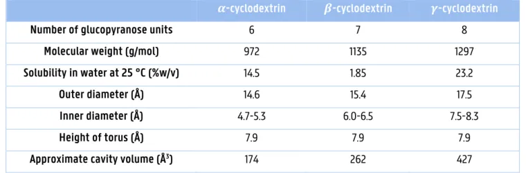
!-Cyclodextrins have unique properties compared with #- and $-cyclodextrins. First, !-cyclodextrins have a larger internal cavity, which can trap larger molecules that cannot be trapped by #- and $-cyclodextrins. Secondly, they have a more flexible structure, which gives a higher solubility than # - and $-cyclodextrins (2). Last, !-cyclodextrins can be rapidly and completely digested by pancreatic amylase and human salivary amylase, which is not capable to digest #- and $-cyclodextrins (2,8). Because of the high bioavailability of !-cyclodextrins they are ideal for specific applications in food and pharmaceutical industries (see 1.1.5.) (2). An overview of the properties of #-, $- and !-cyclodextrins is shown in table 1.1.
Table 1.1.: Properties of cyclodextrins (3,9).
%-cyclodextrin &-cyclodextrin '-cyclodextrin
Number of glucopyranose units 6 7 8
Molecular weight (g/mol) 972 1135 1297
Solubility in water at 25 °C (%w/v) 14.5 1.85 23.2
Outer diameter (Å) 14.6 15.4 17.5
Inner diameter (Å) 4.7-5.3 6.0-6.5 7.5-8.3
Height of torus (Å) 7.9 7.9 7.9
1.1.5. Applications
1.1.5.1. Pharmaceutical applications
!-Cyclodextrins are as a result of their unique properties the best – compared to #- and $-cyclodextrins – carriers for drugs. They can be used to improve the solubility and dissolution of poorly water-soluble drugs and hence the bioavailability and pharmacological effects, which can allow a reduction in dose of the drug. !-Cyclodextrins are used to increase the shelf life of drugs and improve the stability of active pharmaceutical ingredients (2). !-Cyclodextrins can, more effectively than #- and $-cyclodextrins, ameliorate the irritation caused by drugs. On the one hand, the increased drug solubility causes an increased drug efficacy and potency and can, by lowering the dose of the drug, reduce drug toxicity (2). On the other hand active substances that irritate the stomach, skin or eyes can be encapsulated within !-cyclodextrins molecules, which can decrease the local concentration of free active product under the irritancy threshold (2). Also, !-cyclodextrins can be used to reduce the bad smell and irritant or bitter taste of drugs (2,10).
1.1.5.2. Other applications
Cyclodextrins have many other applications in the industries related to agriculture, food (11), chemicals, cosmetics (12), … (2,9). Cyclodextrins are used as multifunctional food ingredients. They protect the active ingredients against oxidation by the complete or partial entrapment of oxygen sensitive food ingredients. Also, they can be used to lower cholesterol levels. For example, BaladeTM low cholesterol butter has been produced by mixing the molten butter with $-cyclodextrins. These cyclodextrins form a stable complex with cholesterol, which can be easily removed from the molten butter (11). In cosmetics, cyclodextrins can protect against loss by evaporation of volatile compounds like perfumes (12). By forming inclusion complexes with cyclodextrins, a large number of insoluble cosmetic components will be more soluble compared to the pure compounds (12). Furthermore, cyclodextrins are used to eliminate undesired odors (12).
1.2. METAL-ORGANIC FRAMEWORKS
Metal-organic frameworks (MOFs) were discovered by Omar M. Yaghi by synthesizing MOF-5, one type of a MOF compound, for the first time (13,14). These MOFs are newly designed crystalline materials made by strong coordination bonds between organic linkers and metal ions or metal clusters forming porous materials (15–17) as shown in Fig. 1.2. MOFs are used for diverse applications such as gas storage (18,19), molecular recognition (18,20), catalysis (18,21), separation science (18,22) and drug delivery (18,23).
When MOFs need to be used as drug carriers, it is important that they are biocompatible. As most MOFs are based on inedible organic linkers and metals such as cobalt or nickel, these MOFs are toxic, mutagenic, carcinogenic and are not acceptable for medical and biological applications (13,15). Efforts have been made to synthesize biocompatible MOFs, but only a few of them are stable, porous and capable of loading biological molecules (15). Some metals such as calcium, zinc, iron, titanium, magnesium and potassium are considered to be biologically acceptable estimated from the toxicity parameter LD50 (Lethal Dose for 50% of the subjects) (13,18). More attention has been paid to biomolecules as organic linkers for the formation of biocompatible active MOFs (13).
Fig. 1.2. General assembly and structure of a Metal-Organic Framework (24).
1.3. CYCLODEXTRIN METAL-ORGANIC FRAMEWORKS
1.3.1. Structure
An original class of biocompatible MOFs has been developed by Stoddart and his co-workers known as cyclodextrin metal-organic frameworks (CD-MOFs) (Fig. 1.3.), which contain edible !-cyclodextrins (15,16,18). !-CD-MOFs combine the cavity structures of !-cyclodextrins and the cage structures of !-CD-MOFs (15).
1.3.2. Synthesis
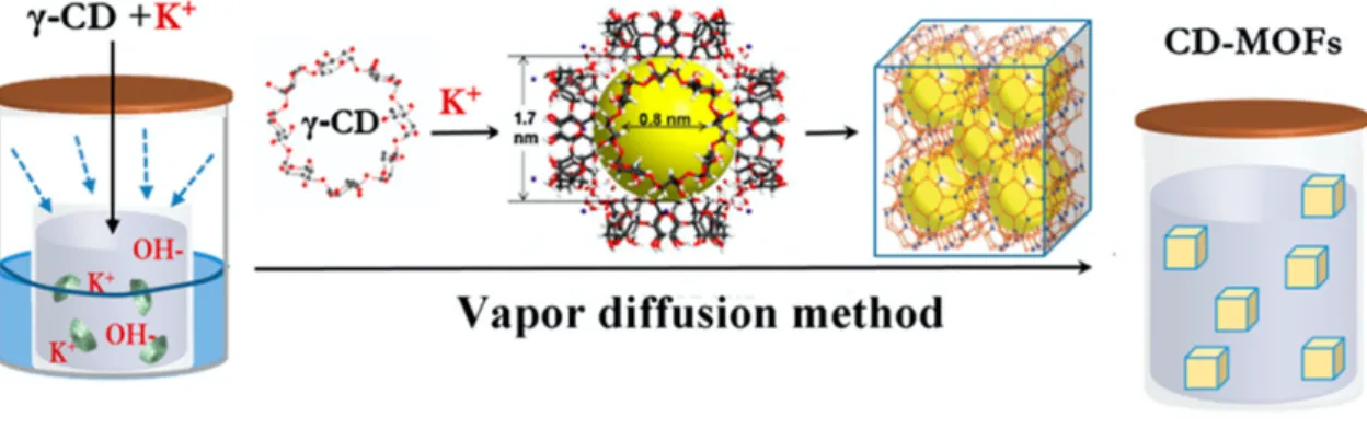
CD-MOF crystals can be synthesized by different methods, but mostly a (modified) vapor diffusion method is used as shown in Fig. 1.4. and Fig. 1.5. (13,16,18).
Fig. 1.4. Vapor diffusion method using KOH and '-CD (adapted from 25).
KOH and !-CD are dissolved in water as the solvent in a glass vial. This vial needs to be placed in a second, larger vial that contains an anti-solvent like methanol (27), which is more volatile. KOH and !-CD should be insoluble in this anti-solvent. The anti-solvent will evaporate and diffuse into the solution of KOH and !-CD, which becomes supersaturated and crystals can start to grow in the solution. This process is called vapor diffusion (28). Classical crystal formation happens in two stages called nucleation and growth, where nucleation is the initial formation of molecular clusters from which crystals grow (29).
Fig. 1.5. Schematic general representation of the vapor diffusion method (28,30)
Several factors have an influence on the size of CD-MOFs. When the temperature is increased, formed !-CD-MOF crystals will be smaller and more uniform without affecting the crystallinity (18). Increased KOH concentration leads to larger !-CD-MOF crystals (18). Changing the solvent (methanol or ethanol) has no influence on the crystal structure of the !-CD-MOF (18). When the reaction time is longer, larger !-CD-MOF crystals will be formed.
1.3.3. Applications
Because of the variety in guest molecules, CD-MOFs are applicable for drug delivery (15). They are also capable of storing small molecules and can be used for gas adsorption (16,18). Recently, CD-MOFs have been used for the separation and purification of petroleum feedstocks (16,31).
1.3.3.1. Drug delivery
Because a lot of potential drug candidates are relatively hydrophobic, an important part of modern controllable drug delivery is developing new formulations that enhance bioavailability and water solubility of active pharmaceutical substances. Great efforts have been made to enhance poor physicochemical and biopharmaceutical properties of some drug molecules by CD-MOF complexation. Furthermore, oral administration routes are desirable as they avoid needles (and thus sterile conditions) and improve patient compliance (26,32). For example, CD-MOF-1 (1.3.5.1.) can be used as a carrier for drugs due to its porous characteristics, water solubility and non-toxic nature (6). One of the most frequently used nonsteroidal anti-inflammatory drugs, ibuprofen, shows a poor solubility as a free acid in physiological and aqueous environment. Ibuprofen’s mechanism of action is the inhibition of cyclo-oxygenase (COX) enzymes, especially the COX-2 enzyme particularly localized in inflammatory cells and tissues. It can be used for the treatment of chronic inflammation and for immediate pain relief. New formulations of ibuprofen should be developed with the aim of increasing its oral bioavailability and rate of uptake as this time is correlated to the rate of onset of the effects. Another goal is increasing the half-life of ibuprofen in the body, proportional to the duration of its effects. Ibuprofen could be incorporated into CD-MOF-1 according to 2 methods. The first approach is a crystallization process analogous to the synthesis of edible CD-MOF-1 (see 1.3.5.2.) using the potassium salt of ibuprofen. The second method is based on absorption, here CD-MOF crystals were prepared using KOH. Next these crystals were washed with ethanol and dried overnight under high vacuum at room temperature. In a series of different solvents containing the free acid form of ibuprofen, these crystals were suspended for five days, allowing the formation of an equilibrium. It was found that maximum loading of ibuprofen is achieved when using more polar solvents. This because the type of solvent is critical in controlling the quantity of ibuprofen absorbed by CD-MOF-1. Using pharmacokinetic data, it was shown that oral administration of the cocrystal (based on CD-MOF-1) results in a similar bioavailability and rapid uptake of ibuprofen compared to the ibuprofen salts. A significant increase of the half-life of ibuprofen was observed in blood plasma. Because of these results, it could be concluded that CD-MOF-1 is effective as a drug delivery vehicle for ibuprofen. This cocrystal of ibuprofen and CD-MOF-1 can be used for acute pain release and an extended analgesic effect (32).
The anti-inflammatory sodium diclofenac is a drug which can be entrapped into porous γ-CD-MOFs, because of the porosity and crystallinity of these materials. These γ-CD-MOFs were synthesized using a vapor diffusion method resulting into crystals suitable for oral delivery (33). Release studies suggested a complex mechanism of release of sodium diclofenac from γ-CD-MOFs with different processes such as diffusion, swelling and erosion which could take place simultaneously during drug release (33).
Fenbufen, belonging to the non-steroidal anti-inflammatory drugs, is a painkiller. It has a poor aqueous solubility which can be enhanced by incorporating fenbufen into CD-MOFs (6).
Lansoprazole, belonging to the proton pump inhibitors, is used to decrease the production of acid in the stomach (6,34). This proton pump inhibitor is insoluble in water and has a lack of stability, thus it is beneficial to encapsulate lansoprazole in CD-MOFs. Lansoprazole-loaded CD-MOFs could be produced using a co-crystallization approach by dissolving lansoprazole, !-cyclodextrin and KOH in 5.0 ml of an aqueous solution. Next, this solution was filtered into a glass vial followed by vapor diffusion with methanol for 24 hours. Crystals could be harvested by filtering and subsequently washing them using ethanol. Last, the lansoprazole loaded CD-MOF crystals were dried overnight under vacuum at 50°C. It was possible to store these crystals in closed vials at room temperature for up to two years (34). PXRD was used for characterizing the crystallinity and showed that the loading of lansoprazole into CD-MOFs does not affect the crystallinity of these CD-MOF crystals (34,35). It was also possible to trap lansoprazole inside CD-MOFs using an impregnation method, but this approach proved to be less effective than the co-crystallization method described above (35).
Valsartan is a drug which is widely used for hypertension to lower the blood pressure of such patients. It is a compound which is water insoluble and thus has a poor oral bioavailability. These properties can be improved by incorporating valsartan in CD-MOFs (36).
Ultraviolet light has the power to damage cells, this can be prevented by ferulic acid which is an antioxidant molecule. By encapsulating ferulic acid in CD-MOF-1 it is possible to improve its thermal instability. It is possible to incorporate ferulic acid into CD-MOF crystals using two methods. First, the crystallization was done using a vapor diffusion method with methanol as anti-solvent into an aqueous solution of KOH, !-cyclodextrin and ferulic acid. Another method was diluting a mixture of !-cyclodextrin and ferulic acid in 500 mL of water. This mixture was left for 1h in the dark under stirring at room temperature. Next, the solution was filtered with collecting the precipitate, which was washed two times with water. Last, the complex was dried in vacuum, becoming a white powder (6).
To treat diseases like asthma, bronchitis and chronic obstructive pulmonary disorders a lot of drugs need to be delivered into the airways using the pulmonary route. This allows targeted drug delivery and a reduced incidence of side-effects. An example of one of these drugs is budesonide, which can be administered in the form of a dry powder inhaler. It is necessary to optimize the carrier of dry powder inhalation to achieve pulmonary delivery of budesonide. For budesonide, nanoporous CD-MOF crystals with uniform inhalation size and cubic morphology can be developed as carrier. To transport drugs into the deeper parts of the lungs, a particle size of 1-5 μm is required, particles with a size over 5 μm will especially be deposited in the upper airways. Efficient systemic absorption is made possible by the large absorptive surface of the lungs, the increased blood flow, the thin distribution pathway to the blood stream and the low metabolic activity. Because of these properties it is possible to avoid first-pass hepatic metabolism of these drugs administrated by inhalation (37).
Coenzyme Q10 (CoQ10), found in human bodies, contains a benzoquinone and an isoprenoid side chain. This coenzyme exists as ubiquinone and ubiquinol (Fig. 1.6.) (38). CoQ10 is an essential compound for the living human body as it is involved in energy production. Furthermore, CoQ10 is supposed to have a role in anti-aging, anti-cancer and antioxidant action and preventing lifestyle-related diseases, which makes CoQ10 a useful component with possible applications in food and medicine (38). When CoQ10 is taken orally, it cannot be absorbed appropriately due to its low water solubility. On top of that, CoQ10 is a compound which is sensitive to light and heat. To improve the bioavailability of CoQ10, it is necessary to increase its solubility and stability by using innovative techniques such as CD-MOF-1 which can be used as edible carrier for CoQ10 (38).
Fig. 1.6. The oxidized ubiquinone form of CoQ10 (A) and the reduced ubiquinol form of CoQ10 (B) (38). Acetaldehyde is an organic anti-fungal agent which is volatile and has an appreciable water solubility. This compound can be encapsulated into and released from the pores of γ-CD-MOF-1 (6,13,39).
A natural triterpene glycoside, glycyrrhizic acid which is isolated from licorice root, shows a wide variety of potential beneficial biological activities such as anti-allergic, anti-inflammatory, antibacterial and anti-cancer properties. It is also known and widely used in food industry as a natural sweetener with a 170 times higher sweetness than sucrose. As glycyrrhizic acid has an extremely low loading efficiency and water-solubility, it limits its own applications. Because of its poor solubility in aqueous gastrointestinal fluids, glycyrrhizic acid has a low oral bioavailability. These properties can be improved by encapsulating glycyrrhizic acid into CD-MOF crystals as an effective carrier for hydrophobic bioactive compounds (41).
Doxorubicin hydrochloride is an effective chemotherapeutic used for the treatment of a variety of tumors such as ovarian cancer, breast cancer and acute lymphoblastic leukemia. Administration of direct anti-cancer drugs shows undesirable side effects and poor pharmacokinetics. Doxorubicin can be encapsulated into CD-MOF-1 (see 1.3.5.1.) (6,43). For effective chemotherapy, targeted and triggered release of doxorubicin exactly at the tumor site is essential, taking into account an extracellular pH of approximately 7.4 and a pH of about 5.5 for tumor cells (43). A release of 15.1% of doxorubicin at pH 5.0 and 7.0% at pH 7.4, which reached a plateau after 12 hours, was noticed for doxorubicin encapsulated into γ-CD-MOF (43).
Honokiol is a bioactive lignan which is insoluble in water. Using CD-MOFs, the bioavailability and oral absorption of honokiol could significantly be improved (42). The solubility of honokiol@CD-MOF was significantly improved in the tested pH range of 1.2-7.4. In a pH 7.4 phosphate buffer the solubility of honokiol@CD-MOF was 19.9 times higher compared to raw honokiol (42). A rapid release was shown for honokiol@CD-MOF with a release of 19% of honokiol in the first two hours of dissolution in the simulated intestinal fluid. After an additional 4 hours of dissolution, the release of honokiol was increased until 46%. Within 24 hours, the release of honokiol@CD-MOF reached a cumulative release percentage of approximately 94% (42). Because of the improved solubility and dissolution rate, it was assumed that honokiol incorporated in CD-MOF could facilitate drug absorption and transport (42).
CD-MOFs can also be used in the encapsulation of 5-fluorouracil, procainamide, antiviral drugs, other anti-inflammatory drugs (such as flurbiprofen, ketoprofen and piroxicam), captopril and many other molecules of interest (26,34,35).
1.3.3.2. Sensors
Due to their water solubility and biocompatibility, CD-MOFs prove to be good candidates for sensors. CD-MOFs have the possibility to encapsulate pH indicators and dyes because of their adsorption properties (13). Because of the incorporation of these chemicals into CD-MOFs, color changes were visually noticed after exposure to specific external stimuli and thus these CD-MOFs were able to sense the environmental status (13). For example, the methyl orange-based pH indicator was encapsulated into CD-MOF-2 for the detection of ammonia or hydrochloric acid by visual observation of colorimetric changes (6,13).
1.3.3.3. Encapsulation of organic dyes for light emission
It is possible to incorporate organic dyes into CD-MOFs for applications in light emission. Recently, a γ-CD-MOF-1 based core-shell structure was synthesized by hierarchical incorporation of different dye molecules. The synthesized core-shell structured CD-MOF retained the luminescence characteristics of both core and shell (13).
1.3.4. Characterization
The crystal structures of !-CD-MOF crystals can be determined by single-crystal X-ray diffraction analysis (18). Scanning electron microscopy and transmission electron microscopy can be used for the morphological characterization (44). The crystallinity of !-CD-MOFs can be characterized by powder X-ray diffraction (18).
1.3.5. CD-MOF overview
An overview of available crystal structures of CD-MOFs deposited with the Cambridge Crystallographic Data Center (CCDC) and their corresponding literature references was made and is shown in table 1.2.
Table. 1.2. An overview of reported CD-MOF structures in literature with their unit cell parameters and space groups (45–48).
Chemical formula Unit cell constants (Å, °) Volume (Å3) Space group
a b c ! " #
(C48H80K2O402+)n, 2n(OH-) (Reference code: LAJLAL)(45)
31.006 31.006 31.006 90.00 90.00 90.00 14904.156 Symbol: I432
Number: 211 (C96H160K4O804+)n, 2n(C7H5O2-), 2n(OH-)
(Reference code: LAJLIT01)(46)
42.652 42.652 28.464 90.00 90.00 90.00 44842.844 Symbol: R32
Number: 155 (C48H80Rb2O402+)n, 2n(OH-)
(Reference code: LAJLEP01)(46)
31.079 31.079 31.079 90.00 90.00 90.00 30019.338 Symbol: I432
Number: 211 (C48H80Cs2O402+)n, 2n(OH-)
(Reference code: LAJKUE01)(46)
30.868 30.868 30.868 90.00 90.00 90.00 29412.062 Symbol: I432
Number: 211 (C96H160Cs4O804+)n, 4n(CH4O), 4n(OH-)
(Reference code: YAPRUE)(46)
24.136 24.136 15.454 90.00 90.00 90.00 9002.674 Symbol: I4
Number: 79 C48H80O40 , 1.23(K+), 0.77(Li+), 2(OH-)
(Reference code: QEFMUM)(47)
43.096 43.096 27.988 90.00 90.00 120.00 44976.662 Symbol: R32
Number: 155
(C42H69CsO35)n, H2O (Reference code: SAZQIW)(48)
15.026 15.265 15.120 90.00 119.19 90.00 3027.590 Symbol: P21
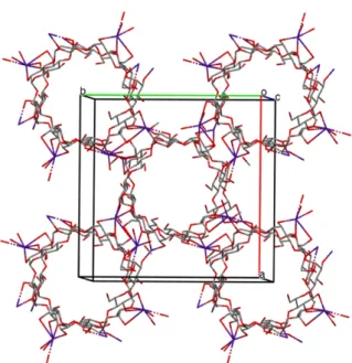
1.3.5.1. (C48H80K2O402+)n, 2n(OH-)
R. Smaldone et al. synthesized CD-MOF-1 (shown in Fig. 1.7.), which has the chemical formula (C48H80K2O402+)n, 2n(OH-), by linking !-cyclodextrin (!-CD) building units by potassium ions. CD-MOF-1 was synthesized using 1.0 equivalent of !-CD (1 mmol, 1.30g) and 8.0 equivalents of KOH (8 mmol, 0.45g) and dissolving these substances in an aqueous solution (20 ml). For 2-7 days vapor diffusion of methanol as anti-solvent (approximately 50 ml) into the solution took place at ambient temperature and pressure. Cubic, colorless, single crystals were obtained suitable for X-ray crystallographic analysis. These crystals were isolated, filtered and washed with methanol (2 times 30 ml) and finally dried (45,46). CD-MOF-1 is stable for solvent removal and has the possibility to store small molecules and gases within its pores (46).
Fig. 1.7. Selected portion of the crystal structure of (C48H80K2O402+)n, 2n(OH-) (45,46). 1.3.5.2. (C96H160K4O804+)n, 2n(C7H5O2-), 2n(OH-)
Just as CD-MOFs can be synthesized using chemicals and conditions used in the research laboratory, it is also possible to prepare CD-MOFs from ingredients of purity and quality suitable for food-safe applications. For example, edible CD-MOF-1 (for CD-MOF-1 see 1.3.5.1.), with chemical formula (C96H160K4O804+)n, 2n(C7H5O2-), 2n(OH-), can be synthesized using food-grade !-CD and either potassium benzoate (a preservative, E212) or a salt substitute (KCl) which are commercially available. These compounds are used in molar ratios identical to these of the chemicals used in the laboratory for the synthesis of CD-MOF-1. Both substances are dissolved in bottled distilled water and for vapor diffusion, Everclear (a certain brand) grain spirit (ethanol) is used instead of methanol, resulting in cubic, colorless crystals (45,46).
1.3.5.3. (C48H80Rb2O402+)n, 2n(OH-)
R. Forgan et al. synthesized CD-MOF-2, which has the chemical formula (C48H80Rb2O402+)n, 2n(OH-), by dissolving 1.0 equivalent of !-CD (1 mmol, 1.30g) and 8.0 equivalents of RbOH (8 mmol, 0.82g) in 20 ml of H2O. These steps were followed by filtering the solution. During 7 days, vapor diffusion with methanol (approximately 50 ml) was allowed to take place. Cubic, colorless crystals were obtained suitable for X-ray crystallographic analysis. Next, these crystals were isolated, filtered and washed with methanol (2 times 30 ml) and finally dried. Analogous to 1, CD-MOF-2 has the possibility to store small molecules and gases within its pores, is stable for solvent removal and is permanently porous. R. Forgan et al. have noted that CD-MOF-2 crystals, grown from RbOH, are the most robust of all the crystals they have investigated so far, because these crystals remain their crystallinity for months (46).
1.3.5.4. (C48H80Cs2O402+)n, 2n(OH-)
R. Forgan et al. synthesized CD-MOF-3, which has the chemical formula (C48H80Cs2O402+)n, 2n(OH-), by dissolving 1.30 g of !-CD (1 mmol) and 0.82 g of CsOH (8 mmol) in 20 ml of H2O. Afterwards, this solution was filtered. During 1 week vapor diffusion using methanol as anti-solvent (approximately 50 ml) was allowed to take place. Under these conditions, two polymorphs CD-MOF-3 and CD-MOF-4 (see 1.3.5.5.) were formed. Moreover, they found out that crystals of these two polymorphs were separated during the same crystallization procedure, but the ratio of CD-MOF-3 and CD-MOF-4 varied between every experiment. Both polymorphs could be separated manually, but some cross-contamination could not be avoided. CD-MOF-3 crystals are colorless, block-like and have the cubic topology such as CD-MOF-1 and CD-MOF-2 (46).
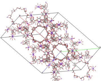
1.3.5.5. (C96H160Cs4O804+)n, 4n(CH4O), 4n(OH-)
During the synthesis of CD-MOF-3 crystals (see 1.3.5.4.), the formation of CD-MOF-4, another polymorphic form was observed. CD-MOF-4, with chemical formula (C96H160Cs4O804+)n, 4n(CH4O), 4n(OH-), has a different morphology compared to CD-MOF-3, which could be analyzed by X-ray diffraction. CD-MOF-4 crystals have the shape of a needle and the results of X-ray diffraction analysis showed a channel-type structure, which is shown in Fig. 1.8. (46).
Fig. 1.8. Selected portion of the crystal structure of (C96H160Cs4O804+)n, 4n(CH4O), 4n(OH-) (46). 1.3.5.6. C48H80O40, 1.23(K+), 0.77(Li+), 2(OH-)
Li/K-CD-MOF, with the chemical formula C48H80O40, 1.23(K+), 0.77(Li+), 2(OH-), was synthesized by dissolving 8.0 equivalents of KOH and LiOH, with varying molar ratios of KOH/LiOH (from Li0.2:K1.4 to Li1.4:K0.2), and 1.0 equivalent of !-CD in 20 ml of H2O. For 15 days vapor diffusion with methanol as anti-solvent (approximately 50 ml) was allowed to take place. These steps resulted in colorless, cubic, single crystals, which could be analyzed by X-ray crystallography. By co-crystallizing LiOH and KOH in a ratio of 1.4:0.2 towards 1.0 equivalent of !-CD, the highest Li+/K+ ratio, K1.18Li0.61, was obtained. When substituting some K+ sites by Li+ ions in CD-MOF-1, it was experimentally demonstrated by PXRD that their extended structures remain intact. When comparing the X-ray diffraction patterns for CD-MOF-1 and Li/K-CD-MOF with the simulated pattern, based on the crystal structure, it was shown that the crystallographic properties remain unchanged when substituting some K+ sites in CD-MOF-1 by Li+ ions in Li/K-CD-MOF. Finally, it was noted that no changes occurred in PXRD patterns of Li/K-CD-MOF when ratios of Li+ ions and K+ ions varied. In Fig. 1.9. the crystal structure of Li/K-CD-MOF is shown (47).
Fig. 1.9. Selected portion of the crystal structure of C48H80O40 , 1.23(K+), 0.77(Li+), 2(OH-) (47). 1.3.5.7. (C42H69CsO35)n, H2O
A rare "-CD-MOF, with chemical structure (C42H69CsO35)n, H2O, was crystalized by J. Liu et al. through a template-induced approach, which was employed for the first time. This CD-MOF, constructed by "-CD and cesium metal salts as building blocks, was used in cytotoxicity assays and for controlled drug delivery. The release speed of drugs and the loading capacity is determined by the shape and size of the pores. The temperature, solvent and ratio of the "-CD to the metal salt are not essential factors that affect the synthesis of this CD-MOF. By single-crystal X-ray diffraction, it was shown that the asymmetric unit is composed of one Cs+ ion and one "-CD molecule. The purity of this CD-MOF, shown in Fig. 1.10, can be confirmed by PXRD (48).
1.4. CORE-SHELL NANOPARTICLES
1.4.1. Structure
Nanoparticles, which have by definition a size between 1 and 100 nm, can be categorized into simple and core-shell or composite nanoparticles. These simple nanoparticles consist of a single material compared to core-shell and composite nanoparticles that are made of 2 or more materials (49,50). Core-shell nanoparticles are composed of an inner material with one set of unique properties, defined as the core and an outer material with a different set of unique properties, defined as the shell (Fig. 1.11.)(25,51).
Fig. 1.11. Schematic representation of a core-shell nanoparticle (52). 1.4.2. Properties
Different properties as biocompatibility, low cytotoxicity and high chemical stability make core-shell nanoparticles multifunctional. These properties depend on the shape, size and type of material used to fabricate the core and the shell (53).
Core-shell nanoparticles can be formed by combining organic and inorganic materials. Four important types of core-shell materials can be distinguished; inorganic, organic-organic, organic-inorganic and inorganic-organic. Materials are chosen in function of the application and type of use of the core-shell nanoparticles (51,53).
Fig. 1.12. Morphologies of core-shell nanoparticles: a) spherical core-shell nanoparticles with or without dense core; b) hexagonal and rod core-shell nanoparticles; c) multiple small core materials coated by single
shell material; d) multi-layered material; e) movable core or well within a hollow shell material (53). 1.4.3. Applications
Owing to the integrated functions of core and shell materials, core-shell structured nanoparticles have been used in the fields of electronics, batteries, medicine, biomedicine, optics and pharmaceutics (53,54).
Core-shell nanoparticles are also used in drug delivery, influenced by the combination of the materials in the core-shell design and the different morphologies. Core-shell nanoparticles with a concentric spherical type morphology are most commonly used as drug dosing vehicles, which control the kinetics of drug release. This is due to the fact that the drug is mostly located in the core, while the shell provides slow diffusion of body fluids into the core and the drug to the outside, which causes an extended release (53).
1.5. X-RAY DIFFRACTION
1.5.1. Historical background
W. C. Röntgen discovered X-rays in 1895 (55). In 1912, Max von Laue discovered that crystals diffract X-rays and that the manner of diffraction could reveal the structure of this crystal. This was the beginning of the technique of single-crystal X-ray diffraction (55,56). In the next few years W.L. Bragg formulated the diffraction law, known as Bragg’s law (equation 1.1.). This law is used to explain the typical X-ray diffraction patterns (55).
1.5.2. Bragg’s law
The Miller indices h, k and l represent a set of parallel planes, which divide the lengths of the unit cell; a, b
and c into equal parts. Miller indices h, k and l correspond with respectively the a, b and c axis that is divided in h, k
and l equal parts. The interplanar spacing is the distance between the parallel planes, which is written as dhkl (28,57).
When X-rays R1 and R2 of a particular wavelength λ hit these parallel (hkl) planes at an angle θ, they will be diffracted at the same angle θ, but only when Bragg’s law is respected (28,57,58);
2dhkl sinθ = nλ (1.1.)
with: d = the distance between parallel planes
n = an integer
λ = the wavelength of the X-rays
θ = the incident angle (the angle between the scattering plane and the incident X-ray)
On Fig. 1.13. it can be noticed that the path length of X-ray R2 equals the path length of X-ray R1 plus an extra distance 2BC (28,57). This path difference can be calculated based on the next following mathematical statement; two angles are the same when corresponding sides are perpendicular (57). This means that the angle CÂB is identical to
θ. As seen in Fig. 1.13. the triangle ABC is right-angled, which means that sinθ = BC/AB. When AB is replaced by d, the formula is transformed into; BC = dsinθ. At last this gives the result of 2BC = 2dhklsinθ, which is the difference in path
length. When 2BC corresponds with an integral number of the wavelength (nλ), constructive interference will occur. If not, there will be destructive interference (57,59).
1.5.3. Reciprocal space
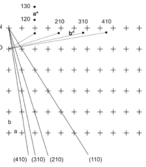
Reciprocal lattices will be used to determine the direction of the diffracted X-rays (28). This concept was introduced by Paul Peter Ewald in 1921. This reciprocal lattice establishes a link between the unit cell constants and the interplanar dhkl distances (60). To construct the reciprocal lattice, shown in Fig. 1.14., an arbitrary lattice point O
has to be chosen as the origin. From this origin, a vector with length 1/dhkl has to be drawn, perpendicular to the (hkl)
plane. The reciprocal lattice points with coordinates h, k and l is given by the end of these vectors (29,60). The reciprocal unit cell parameters were converted from the unit cell parameters (58,61);
a* = ! # $ % , b* = & # $ % , c* = & # ! % (1.2.)
with: a*, b* and c*: reciprocal lattice vectors
a, b and c: Bravais lattice vectors (see 1.5.6.1.)
V: volume of the unit cell
Fig. 1.14. Construction of the reciprocal lattice in two dimensions. The plus (+) signs and dots represent real lattice points and reciprocal lattice points respectively (29).
1.5.4. Ewald’s sphere
In the reciprocal space, Bragg’s law can be visualized as Ewald’s sphere. By drawing the incident X-ray through the origin of the reciprocal lattice (point O in Fig. 1.15.), and then drawing a sphere through this same origin with a radius 1/λ (with the wavelength of the X-ray beam) centered on the direction of the incident beam (XO), Ewald’s sphere is constructed.
A reflection is possible in the direction of P (a reciprocal lattice point), only if this point is situated on the circle (28,60). The equation sinθ = OP/BO = OP/2λ applies to the rectangular triangle PBO. Rearranging this formula gives; (2/OP)sinθ = λ. When P is a reciprocal lattice point, OP can be replaced by 1/dhkl resulting in the satisfaction of
Bragg’s law (60). Each reciprocal lattice point that crosses with the Ewald's sphere conforms to Bragg’s law, so these points result in diffraction (see Fig. 1.15.)(28,61). The reciprocal space must be rotated around the origin to obtain all possible reflections, because a stationary crystal in the X-ray beam would result in a limited quantity of reciprocal lattice points crossing the circle. This rotation is performed by rotating the crystal in different directions, this causes other reciprocal lattice points (P’) crossing the circle at a different moment, resulting in another reflection (61,62).
Fig. 1.15. Schematic representation of the Ewald construction by combining Bragg’s law and the reciprocal lattice. When the reciprocal lattice point P crosses the circle, beam R will diffract from the crystal (29).
1.5.5. Powder X-ray diffraction
In powder X-ray diffraction, the sample is usually a powder consisting of fine grains of single crystalline material, instead of an individual crystal. The term powder stands for the crystalline domains that are randomly oriented in the sample. The X-ray source is usually an X-ray tube which focuses the X-rays on the sample at an angle
θ. The intensity of the diffracted X-rays is measured by the detector, which has an angle of 2θ with respect to the incident X-ray beam (63,64). There are different possible diffraction directions of the crystal lattice, these should all be reached by measuring the sample across a range of 2θ angles (65). Fig. 1.16. shows the composition of a powder X-ray diffractometer.
.
Fig. 1.16. Schematic composition of a powder X-ray diffractometer (63).
A diffraction pattern is obtained, which shows concentric rings of scattering peaks. These peaks are corresponding to the various spacings in the crystal lattice (66). An X-ray powder diffractogram plots intensity against the angle of the detector, 2θ (63). The underlying structure of the material can be determined because of the specific positions and intensities of the peaks in the diffractogram (66). When Bragg’s law (see 1.4.2.) is fulfilled, constructive interference will be produced because of the interaction between the sample and the incident X-rays (30,65).
1.5.6. Single-crystal X-ray diffraction
Single-crystal X-ray diffraction is an extremely powerful analytical technique that is able to give an insight into the structure of complex molecules (67,68). Single-crystal X-ray diffraction is performed by irradiating single crystals. The incoming X-ray beam will be diffracted by the crystal, where the orientation and the intensity of the diffracted X-ray beams can be measured, and a diffraction pattern is obtained. From these measurements the electron density of the atoms within the molecule can be calculated (30,68). By interpreting the electron density, a detailed model of a molecule and atoms in a single crystal can be obtained (30,57).
1.5.6.1. Crystals
Crystals are defined as solid materials consisting of atoms, molecules or ions that are ordered in a symmetrical pattern, that is repeated over the entire crystal (28,59). The unit cell, as seen in Fig 1.17., is the smallest building block of a crystal. This unit cell is defined by six parameters: a, b and c as the lengths of the cell and the three angles between them; α (b ⋀ c), β (a ⋀ c), and γ (a ⋀ b) (28,57,59).
Fig. 1.17.Presentation of a unit cell (A) in a crystal lattice (B) (58).
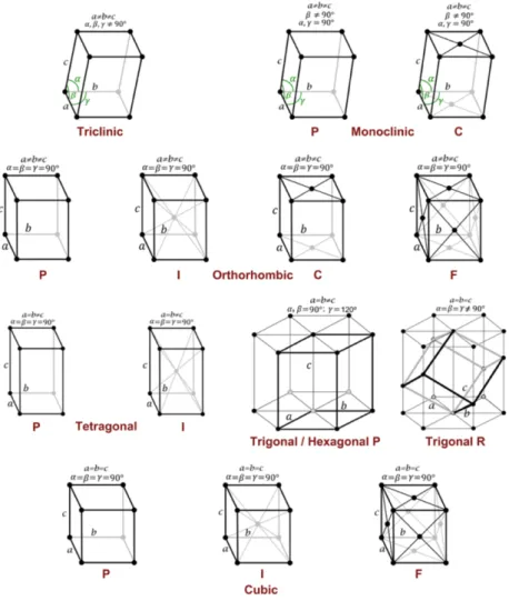
Seven crystal classes are based on possible combinations of these parameters; triclinic, monoclinic, orthorhombic, tetragonal, trigonal, hexagonal and cubic. Together with the unit cells, which can be divided in 4 types; primitive (P), body-centered/internal (I), face centered (F) and side centered (C), 14 types of different possible lattices can be defined. These are called the Bravais lattices and are presented in Fig 1.18. (28,57,59).
These Bravais lattices define the symmetry and shape of the unit cell (68). When all the symmetry operations are combined with these 14 Bravais lattices, 230 possible space groups are generated (57,58). These space groups are the symmetry groups of 3D crystal structures (58).
1.5.6.2. X-ray diffraction
To get a proper single-crystal X-ray diffraction pattern, suitable crystals will be selected and harvested on small polymer loops like cryoloops or LithoLoops (30,68). This cryoloop is placed in the central position of the goniometer, which ensures that the crystal will always be positioned in the X-rays (30). During the measurement, the crystal is flash-cooled at 100 K by evaporation of liquid nitrogen on the crystal (30,68). Because of this lower temperature, the molecules will thermally vibrate less and it prevents crystal decay by radiation, which prolongs the lifetime of the crystals (28). It may be required to protect the sample for cryocooling by adding a cryoprotectant. This ensures that the water in the sample cannot be converted into ice and thus prevents the sample from breaking and prevents ice-ring formation – because of water present on the crystal surface - visible in the diffraction patterns (30,68).
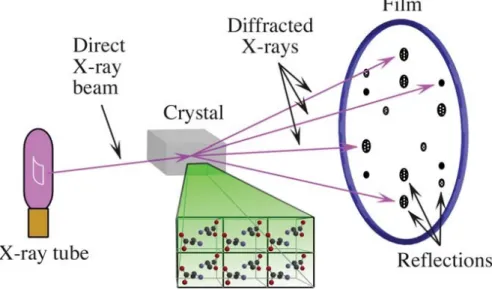
On Fig. 1.19. it can be seen that between the X-ray source (X-ray tube in Fig. 1.20.) and the X-ray detector, a crystal is mounted (29,57). A direct X-ray beam leaves the X-ray tube, this X-ray will be diffracted by the crystal. Dark spots, also called reflections, appear where the diffracted X-rays hit the detector. These reflections can be visualized in different ways. The greater the intensity of the diffracted X-ray beam, the darker and broader these spots (29,57).
Fig. 1.19. Representation of a crystal that diffracts the X-rays, which results in reflections where the diffracted X-rays hit the detector (29,57).
1.5.6.3. X-ray diffractometer
An X-ray diffractometer is composed of three basic elements; a sample holder, an X-ray tube and an X-ray detector (69). For the determination of molecular structures, X-rays are suitable, because the wavelength of X-rays vary between 0.1 and 10 nm. This is similar to the lengths of the bonds between atoms in a molecule (30).
In a vacuum tube, which consists of a filament and a water cooled anode, X-rays are generated (Fig. 1.20.)(28– 30,69). This filament is heated by an electric voltage to produce electrons, which are sent to a molybdenum or copper anode. These electrons will produce heat and X-rays when they hit the anode surface, but only 1% of the electrical energy will be converted into X-rays (28,30). When the anode is molybdenum, the wavelength of the produced X-rays will be 0.71 Å. But, the wavelength of the produced X-rays will be 1.54 Å when the anode is copper. When using molybdenum, the spots will have a lower intensity because this radiation is less diffracted than copper (28). The obtained X-rays can leave the tube trough a beryllium window to the sample. This beryllium window is highly toxic and all contact with this window should be avoided when replacing the tube (28,30).
Fig.1.20. Schematic representation of an X-ray tube (29,30).
When Bragg’s law (see 1.4.2.) is satisfied, constructive interference will be produced because of the interaction between the sample and the incident X-rays (59). By rotating the crystal, diffraction patterns of each unique orientation can be obtained, and all data can be collected. This is necessary because of the 3D structure of the crystal (57). A detector will collect the diffracted X-rays (28). The diffractometer that was used in this thesis is a Rigaku Oxford Diffraction dual wavelength (Cu, Mo) SuperNova with an Atlas Charge Couple Device (CCD) detector. X-rays will be converted into electrons, which will accumulate on pixels of the detector. By flipping the voltage of the pixel rows, these electrons can be read out and an electric current is obtained (See Fig. 1.21.)(28–30). Reflection spots will be generated with the intensity in proportion to the electric current (30).
Fig. 1.21. Schematic representation of a CCD detector (28–30).
Structures can be solved using the graphical user interface Olex2 with the ShelXS structure solution program using Direct Methods. Refinement is performed with the ShelXL refinement package, using Least Squares minimization (28,30).
1.6. LUMINESCENCE
1.6.1. Temperature dependent luminescence
An important parameter of the intracellular environment is the temperature, as it changes the reactivity of biomolecules (70). Tumorous cells can cause temperature changes (71). Because of their faster metabolic rate, they produce more heat than normal cells (72). It is suggested that there is a correlation between the degree of malignancy of the tumor and the amount of temperature rise. The hotter the tumor, the more virulent its biological nature. The use of suitable temperature measuring devices is of great value in early cancer diagnosis (71).
Luminescence is defined as the emission of light from a certain substance, obtained from electronically excited states caused by an external excitation source like optical radiation in the case of photoluminescence (73).
1.6.2. Luminescence nanothermometry
Macroscale changes in the body’s heat content are reported by temperature measurements. These measurements are based on repeatable physical manifestations of molecular effects and are crucial in scientific research and development. Among traditional temperature sensors, which have many intrinsic limitations and are not suitable for temperature measurements of fast-moving objects or objects at submicron scale, luminescence-based thermometry is proving to be a promising alternative.
Temperature measurement methods can be classified into three different categories, which depend on the nature of contact between the object of analysis and the sensor (74,75);
• Invasive; there is a direct contact between the monitoring device and the medium of interest. • Semi-invasive; remote observation is allowed by treating the medium of interest in a certain way. • Noninvasive; the medium of interest is observed remotely.
Nanothermometry is intended to access knowledge of the local temperature of a certain system. This knowledge is needed to understand micrometric and nanostructured systems whose dynamics and performance are determined by temperature (73). Luminescence thermometry is based on luminescent probes with strongly temperature dependent emission properties (76). Because different applications require different properties, a universal thermal sensor does not exist. For example, nanothermometers in biomedicine should be water soluble, non-toxic and very stable under light radiation which makes that toxic components cannot be delivered to cells. For biological thermometers, very accurate precision is important as the difference between e.g. 38°C and 40°C has to be detected (73).
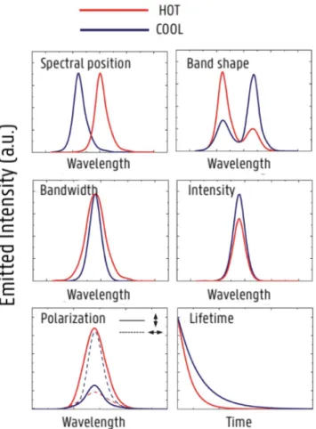
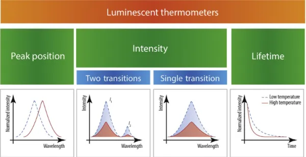
The relationship between temperature and luminescence behavior in a material is represented by luminescence-based thermometry (75). Based on the specific parameter of luminescence that is analyzed, luminescence nanothermometry can be grouped into different classes. The luminescence emission of a certain material can be defined by six parameters; band intensity, spectral position, band-shape, lifetime, polarization and bandwidth (Fig. 1.22.) (73,75).
One of the luminescence nanothermometry subclasses is Intensity Luminescence Nanothermometry (ILNth), which is the most often explored technique. Here, thermal sensing is obtained through the analysis of the intensity of the luminescence. When temperature changes, there will be a change in the quantity of emitted photons per second, which means that the emission spectrum becomes less or more intense (73). This class includes ratiometric thermometers as they are based on the intensity ratio of 2 emission peaks. Organic compounds, such as dyes, can be used to develop ratiometric thermometers (75).
Fig. 1.22. Schematic representation of possible effects caused by temperature increment on the luminescence (73).
Rhodamine B, an organic, fluorescent dye, shows a unique emission intensity, which is temperature-dependent. Because of local fluctuations in light intensity and dye concentration, which causes changes in fluorescence signal, the use of Rhodamine B is not good enough to ensure accurate temperature data. Hence it’s necessary to incorporate a reference dye (such as Rhodamine 110) into the Rhodamine B solution, which allows the temperature to be measured as the ratio of both emission peaks (ratiometric), independent of local variations (76,77). With increasing temperature, the fluorescence intensity of RhB decreases (77).
In luminescent thermometry, three main approaches are followed to determine the temperature (Fig. 1.23.); • The spectral shift of a given transition.
• Measurements of the emission intensity, using the integrated intensity of a single or of a pair of transitions, moreover, the peak maxima can also be used.
Fig. 1.23. Classification of luminescent thermometers (74).
To compare the performance of different luminescence thermometers, following parameters are used; relative thermal sensitivity, temperature uncertainty, spatial and temporal resolution and repeatability and reproducibility.
The integrated intensity is converted into temperature by the thermometric parameter ∆ defined as;
∆ = ') '( (1.3.) with: ∆: thermometric parameter
I1 and I2: integrated intensities of two transitions
The relative change of ∆ per degree of temperature change (%K-1) is indicated by the relative thermal sensitivity Sr, which is defined by (74,75);
Sm is indicated as the maximal value of Sr and Sr should be as high as possible.
Compared to Sa (the absolute sensitivity), the relative thermal sensitivity has often been used to compare different thermometers, independent of their nature. Through this independence it is possible to compare different materials direct and quantitative, this makes Sr a powerful tool when different techniques are considered. Because Sa depends on experimental setup and sample characteristics, this parameter cannot be used to compare the performance of different luminescent thermometers (74,75).
The TeSen Calculator tool is an easy-to-use program, which allows quick analysis of data considering on one hand the peak maxima and the surface areas under the peak and on the other hand testing the ratio of multiple peaks, different temperature ranges and different peak ranges (75). This tool can be used to calculate thermometric parameters as the absolute sensitivity Sa and relative sensitivity Sr values, using the different ∆ equations simultaneously. This can be done for any kind of ratiometric sensor material, which is based on the steady state intensity change of two transition peaks (75).
Thermometric systems can be classified as primary or secondary thermometers. Primary thermometers are characterized by an established state equation, which relates a certain measured value directly to the absolute temperature without need for calibration. This is in contrast to secondary thermometers, which need a reference to a known temperature for their calibration (74). For secondary thermometers, used in our lab, two important trends for the temperature evolution of the thermometric parameter can be identified. First of all, emission derived from a single center, modeled by an exponential curve. When I1 and I2 correspond to transitions of the same emitting center this exponential curve is observed. Second, emission derived from two different centers, modeled by an S-shaped, sigmoidal curve. When the host matrix or ligands play an important role in the energy transfer mechanisms, an S-shaped curve appears. While for the first case, calibration is independent of the host material, in the second group the matrix can tune the thermometer’s sensitivity (74).
1.6.3. Dyes
1.6.3.1. Rhodamine B
Rhodamine B (C28H31ClN2O3), presented in Fig. 1.24., is a xanthene dye and an organic chloride salt. It’s an amphoteric dye which is used as a fluorescent dye. Rhodamine B appears as a reddish powder or green crystals, which is soluble in water and methanol. Safety precautions should be taken as rhodamine B is corrosive and irritant (78,79). Rhodamine B its luminescence is temperature dependent (80), which is important for the further applications.
Fig. 1.24. Schematic structure of Rhodamine B (IUPAC: [9-(2-carboxyfenyl)-6-di-ethylaminoxanthen-3-ylidene]-di-ethylazaniumchloride) (78).
1.6.3.2. Fluorescein
Fluorescein (C20H12O5), presented in Fig. 1.25., is an organic compound, which is the most commonly used fluorescent probe. It is widely used as a synthetic coloring agent. Fluorescein appears as a deep red powder. It’s a dye which is insoluble in water, but soluble in methanol or ethanol. Safety precautions should be taken as fluorescein is irritant (81,82). Fluorescein can be used as a fluorescent indicator, because it changes from colorless to green fluorescent around pH 4-4.5 (81).
2. OBJECTIVES
CD-MOFs, an original class of biocompatible MOFs was developed by Stoddart and co-workers. These CD-MOFs have the cavity structures of !-cyclodextrins and the cage structures of MOFs. To synthesize CD-MOFs, mostly a vapor diffusion method is used (15). The crystal structures of !-CD-MOF crystals can be determined by X-ray diffraction analysis, which is an extremely powerful analytical technique that is able to give an insight into the structure of complex molecules (18). For biological applications, core-shell nanoparticles with a size between 1 and 100 nm, can be applied (50). These core-shell nanoparticles are composed of an inner material with one set of unique properties, defined as the core and an outer material with a different set of unique properties, defined as the shell (25).
The aim of this work is to develop novel temperature nanosensors, based on core-shell nanoparticles of !-CD-MOFs with incorporated dyes, such as rhodamine B and fluorescein, more specifically in the core and shell, respectively.
First, starting from !-CD and KOH, !-CD-MOF crystals will be synthesized in a vapor diffusion method using methanol as anti-solvent (see 3.1.). With single-crystal X-ray diffraction, the molecular crystal structures of these !-CD-MOF crystals will be analyzed. Next, !-CD-MOF⊃RhB/FL crystals will be synthesized using the same vapor diffusion method (see 3.2.). Rhodamine B is an amphoteric, xanthene dye and an organic chloride salt, which is used as a fluorescent dye, while fluorescein is an organic compound, which is widely used as a synthetic coloring agent. These !-CD-MOF⊃RhB/FL crystals will be analyzed using powder X-ray diffraction to compare the structure of the bulk material with the already determined crystal structures. Subsequently, !-CD-MOF core-shell crystals will be produced (see 3.3) and different dyes will be incorporated into the core and shell, i.e. more specifically rhodamine B into the core and fluorescein into the shell. This synthesis is based on a vapor diffusion method using methanol as anti-solvent. The final objective is the synthesis of core-shell nanoparticles of !-CD-MOFs with rhodamine B and fluorescein incorporated into the core or shell. The purpose of making these core-shell materials at nanoscale is to be able to use them in biological applications such as luminescence temperature sensing in cells. This is because the luminescence of these dyes is temperature-dependent, which makes that these !-CD-MOFs can serve as temperature sensors for tumor cells, in which the malignancy of these tumors is related to their temperature. The luminescence of these dyes will be studied by luminescence studies.
3. MATERIALS AND METHODS
3.1. SYNTHESIS OF !-CD-MOF CRYSTALS
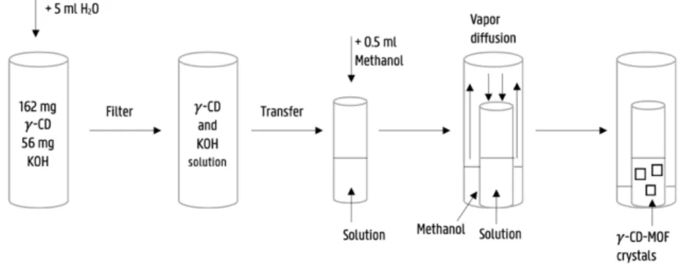
56 mg KOH and 162 mg !-CD were added to a vial of 25 ml. Subsequently, 5 ml H2O was added to dissolve the KOH and !-CD. The obtained solution was then filtered through a small filter paper with a pore size of 4-7 μm and a diameter of 90 mm. Next, the solution was transferred into a small vial of 4 ml and 0.5 ml of methanol was added. This small vial was placed in a second, larger vial of 25 ml containing approximately 5 ml of methanol. The larger vial was closed with a snap-on-lid and stored at room temperature for four days, allowing vapor diffusion to take place. After four days, !-CD-MOF crystals were formed, suitable for single-crystal X-ray diffraction analysis. This process is described in Fig. 3.2. In Fig. 3.1. the X-ray diffractometer used in this thesis is shown.
Fig. 3.1. Rigaku Oxford Diffraction dual wavelength (Cu, Mo) SuperNova equipped with an Atlas CCD detector (Rigaku Oxford Diffraction, Yarnton, UK).