DECARBONISATION OPTIONS
FOR THE DUTCH GLASS FIBRE
INDUSTRY
R. Krijgsman, M. Marsidi
21 November 2019
Decarbonisation options for the Dutch glass fibre industry
© PBL Netherlands Environmental Assessment Agency; © ECN part of TNO The Hague, 2019
PBL publication number: 3721
TNO project no. 060.33956 / Publication number: TNO 2019 P11185
Authors
R. Krijgsman and M. Marsidi
Acknowledgements
Arjette Arkema and Roelof Vedder from Electric Glass Fiber NL, B.V. Nippon Electric Glass.
MIDDEN project coordination and responsibility
The MIDDEN project (Manufacturing Industry Decarbonisation Data Exchange Network) was initiated and is also coordinated and funded by PBL and ECN part of TNO. The project aims to support industry, policymakers, analysts, and the energy sector in their common efforts to achieve deep decarbonisation. Correspondence regarding the project may be addressed to: K.M. Schure (PBL), Klara.Schure@pbl.nl, or A.W.N van Dril (TNO), Ton.vanDril@tno.nl.
Production coordination
PBL Publishers
This publication is a joint publication by PBL and ECN part of TNO and can be downloaded from: www.pbl.nl/en. Parts of this publication may be reproduced, providing the source is stated, in the form: Krijgsman, R. & Marsidi, M. (2019), Decarbonisation options for the Dutch glass fibre industry. PBL Netherlands Environmental Assessment Agency and ECN part of TNO, The Hague.
PBL Netherlands Environmental Assessment Agency is the national institute for strategic policy analysis in the fields of the environment, nature and spatial planning. We contribute to improving the quality of political and administrative decision-making by conducting outlook studies, analyses and evaluations in which an integrated approach is considered paramount. Policy relevance is the prime concern in all of our studies. We conduct solicited and
unsolicited research that is both independent and scientifically sound.
ECN part of TNO has a twofold mission: to accelerate the energy transition and to strengthen the competitive position of the Netherlands. ECN part of TNO conducts independent and internationally leading research and we stand for an agenda-setting, initiating and supporting role for government, industry and NGOs.
This report was reviewed by Arjette Arkema and Roelof Vedder from Electric Glass Fiber NL, part of Nippon Electric Glass. PBL and ECN part of TNO remain responsible for the content. The decarbonisation options and parameters were explicitly not verified by the companies.
Contents
Summary 4
INTRODUCTION
5
1
CONTINUOUS GLASS FIBRE PRODUCTION IN THE NETHERLANDS
6
1.1 General info 6
1.2 History of Electric Glass Fiber NL, B.V. 7
2
CONTINUOUS GLASS FIBRE PROCESSES
8
2.1 Production processes 8
2.2 Specific energy and material consumption 12
2.3 Emissions 14
2.4 Investment costs 15
3
CONTINUOUS GLASS FIBRE PRODUCTS AND APPLICATION
16
3.1 Product Descriptions 16
4
OPTIONS FOR DECARBONISATION
17
4.1 Energy efficiency, waste heat use 17
4.2 Recycling 17 4.3 Electrification 18 4.4 Hydrogen use 19 4.5 Upgraded biogas 19
5
DISCUSSION
20
REFERENCES
21
FINDINGS
Summary
Continuous glass fibre production in the Netherlands takes place at Electric Glass Fiber NL, B.V. in Westerbroek, Hoogezand, part of Nippon Electric Glass. The company produces 75–80 kilotonnes (kt) of continuous glass fibre annually, used for mechanical reinforcement of plastics and other products. From 2013 to 2017, its annual CO2 emissions amounted to 39–
42 kt. CO2 emissions mostly originate from natural gas combustion during the glass smelting
furnace process, and subsequent process steps. About 6%–7% of the CO2 emissions are
process emissions from the glass forming reaction. The energy use of natural gas amounts to 0.65 to 0.71 PJ, per year. Final electricity use for various purposes amounts to 0.22 to 0.24 PJ per year.
Examples of on-site decarbonisation options are:
• Electrification of the furnace, which will be applied for 25% (boosting) in the new furnace that Electric Glass Fiber NL, B.V. is currently constructing. Further study is needed to determine the potential of other electrification options for heat (e.g. forming process);
• Replacing natural gas with renewable alternatives. Hydrogen application in the furnace is limited because of the low radiative flame capacity. Replacing natural gas with biogas is possible;
• Improve energy and material efficiency. Further energy efficiency improvement may be achieved with the new furnace and filament forming departments to reduce heat losses. Optimisation of production processes can reduce the share of rejected material in forming. Further application possibilities of waste heat can be explored (e.g. for district heating).
FULL RESULTS
Introduction
This report describes the current situation for the Dutch continuous glass fibre production in the Netherlands and the options and preconditions for its decarbonisation. The study is part of the MIDDEN project (Manufacturing Industry Decarbonisation Data Exchange Network). The MIDDEN project aims to support industry, policymakers, analysts, and the energy sector in their common efforts to achieve deep decarbonisation. The MIDDEN project will update and elaborate further on options in the future, in close connection with the industry.
Scope
In the Netherlands, one plant produces continuous glass fibres: Electric Glass Fiber NL, B.V. This plant is part of Nippon Electric Glass (NEG). The plant is situated in Westerbroek (Midden-Groningen municipality).
In the Netherlands, producers include: Electric Glass Fiber NL, B.V. (Hoogezand) Production processes include: Mineral melting, forming, curing, drying, chopping. Products include: Continuous glass fibre (dry and wet chopped strands).
The main options for decarbonisation are electrification of the furnace and other processes requiring heat, fuel switching from natural gas to hydrogen or biogas, and reducing material and waste heat losses.
Reading guide
Section 1. introduces the Dutch continuous glass fibre industry. Section 2 describes the current continuous glass fibre production processes in the Netherlands. This includes the material and energy inputs, emissions, equipment and costs of current continuous glass fibre production. Section 3 describes the relevant products and their applications, while options for decarbonisation are systematically quantified and evaluated in 4. The feasibility of and requirements for those decarbonisation options are discussed in Section 5.
1 Continuous glass
fibre production in the
Netherlands
Continuous glass fibre is mainly used for reinforcing plastics and other materials in various applications. Continuous glass fibre is one of the smallest sectors in the glass industry in terms of production volumes, but has a relatively high value-to-mass ratio (JRC, 2013).
1.1 General info
Nippon Electric Glass (NEG) is the world’s biggest manufacturer of specialty glass. In 2016, it acquired all of PPG’s European fiberglass business unit to expand its operations (Gough, 2017). The Dutch venture was named Electric Glass Fiber NL, B.V. (EGF-NL). Its only location is in Westerbroek, a municipality in the Dutch Province of Groningen. In Table 1, general info of Electric Glass Fiber NL, B.V. is provided.
Table 1 Electric Glass Fiber NL, B.V. general info
Characteristics Electric Glass Fiber NL, B.V. Name Electric Glass Fiber NL, B.V.
Address Energieweg 3
Postal code 9608PZ
City Westerbroek
Emissions (2017, tonne CO2) 39010
Employment (2018) 450 employees1
Corporate group Nippon Electric Glass Co. Ltd.
Electric Glass Fiber NL, B.V.
Electric Glass Fiber NL, B.V. has an estimated annual production output of 75,000 (NPAL, 2019) to 80,000 tonnes (Nippon Electric Glass, 2018) of E-glass2. The melting throughput
capacity amounts to around 95,000 tonnes. Electric Glass Fiber NL, B.V. has announced plans to increase the production capacity to 165,000 tonnes by building a new 120,000 tonne melting furnace, replacing one of the current two furnaces.
Electric Glass Fiber NL, B.V. is situated in a relatively isolated location, between the cities of Groningen and Hoogezand, alongside the Winschoterdiep canal. This area is located around 10 km east of the city of Groningen.
1 After installing the new production line, employment is expected to increase by 100 FTEs (MER, 2018). 2 ‘E’ because of initial electric applications.
Global production of continuous glass fibre
On a global basis, the United States is the largest producer of continuous glass fibre, with 40% of the worldwide output in 2005. Europe and Asia accounted for a respective 20% and 25% output in that same year (JRC, 2013). In the EU, there were 17 continuous glass fibre production plants in 2005 with a combined total of 34 furnaces in operation (Table 2).
Table 2 Continuous glass fibre installations and furnaces in EU Member States (JRC, 2013)
Member State Number of installations Number of furnaces (in operation in 2005) EU-25 production Germany 3 5 Belgium 2 5 Czech Republic 2 4 France 2 4 Italy 2 3 Finland 1 3 Slovakia 1 3 The Netherlands 1 2 United Kingdom 1 2 Spain 1 2 Latvia 1 1 Total 17 34 933,400 tonnes in 2005
Continuous glass fibre production plants can vary in capacity from less than 50 tonnes/day to over 100 tonnes/day (Table 3).
Table 3 Number of continuous filament furnaces in specified production ranges (JRC, 2013) Production range (tonnes/day) <50 50 to 100 >100 Number of furnaces in each range (2005) 11 11 12
1.2 History of Electric Glass Fiber NL, B.V.
The company PPG (Pittsburgh Plate Glass) was founded in 1883. After successful expansions to Europe in the 1900s, it added continuous glass fibre to its portfolio of products in 1952. The company initially started producing E-fibre for circuit board and plastics reinforcement. The Silenka factory in Hoogezand, founded in 1963, was originally a joint venture between PPG and AKU (Akzo). PPG acquired full ownership of the plant in Hoogezand from Silenka in 1991. In 2016, PPG sold its continuous European glass fibre business unit, including the production plant in Hoogezand, to the Japanese company Nippon Electric Glass Co. Ltd. (NEG3). The name of the Hoogezand plant was changed into Electric Glass Fiber NL B.V.
Electric Glass Fiber NL, B.V. produces E-glass chopped strands, which are rice grain size cutlets.
3 NEG has been around for over 70 years, mainly producing in Asia and recently expanding its operations with
PPG’s Fiberglass operations (Nikkei Asian Review, 2019). NEG has one other production location in Europe in the UK and one sales office in Germany.
2 Continuous glass
fibre processes
2.1 Production processes
Continuous glass fibre is produced by melting sand, clay, quicklime and dolomite at 1600oC
in a furnace. The melting furnace at Electric Glass Fiber NL, B.V. runs primarily on natural gas. The melt is refined and then transported in heated channels to the forming
departments. There the filaments are formed by gravity. The filaments are directly water and air cooled as they are pulled out of the bushings and wound up on spindles. Before winding, a resin coating is applied on the filament for protection and properties like water repellence. For their final form, the fibres are unwound again and divided into the production line of their application (wet or dry chopped strands). The dry chopped strands are dried using a natural gas fired curing oven (at 200 oC). Finally, the products are packaged and prepared for
transport to the customers.
The biggest material losses occur during forming (15%) and chopping (5%). Part of the losses can be recycled and used again as input material. The losses from chopping after the curing oven cannot be recycled due to the cured binder attached to the material. The internal waste amounts to about 11–12 kt, annually (Gedeputeerde staten van de provincie
Groningen, 2019).
An overview of the process is presented in Figure 1. The blue lines represent the main flow of materials.
CO2 emissions are emitted during natural gas combustion in the melting furnace and curing
ovens, as well as from process emissions from minerals, for example dolomite. The furnace runs continuously until the end of its lifetime (around 7 to 8 years). The current production level is around 80 kt production per year (Nippon Electric Glass, 2018). The current capacity is around 95 kt/yr molten glass capacity (WMB, 2007).
Figure 1 Overview of the production process
The production processes are described in more detail below.
2.1.1 Batch preparation and melting
The main input materials generally used in the continuous glass fibre industry are described in Table 4. Fuel oils for the furnace have been phased out gradually.
The ingredients are brought to the plant per silo bulk truck (Gedeputeerde staten van de provincie Groningen, 2019). The costs of these basic minerals are relatively low, although specific qualities are required. The coating materials may possibly be more expensive.
Table 4 Materials used in continuous glass fibre production (JRC, 2013)
Description Materials Glass-forming materials Silica sand
Glass intermediate and modifying materials
Calcium carbonate, calcium oxide, alumina silicate, colemanite, calcium borate, borax, boric acid, feldspar, fluorspar, calcium sulphate, sodium carbonate,
potassium carbonate, sodium sulphate, zinc oxide, titanium oxide or rutile, zirconium oxide, dolomite and iron oxide
Coating materials The coating material will vary depending on the end use of the product. Typical coatings are: film formers (e.g. polyvinyl acetate, starch, polyurethane, epoxy resins); coupling agents (e.g. organo-functional silanes); pH modifiers (e.g. acetic acid, hydrochloric acid, ammonium salts); and lubricants (e.g. mineral oils, surfactants)
Fuels (Fuel oil), natural gas, electricity
Water Mains supply and local natural sources
Ancillary materials Packaging materials including plastics, paper, cardboard, etc.
Process gases, oxygen
Water treatment chemicals for cooling water and waste water
Silica, calcium oxide (CaO, quicklime), dolomite and clay are the main ingredients for producing continuous glass fibre. Silica sand (SiO2) is the largest component and is a
network former. Quicklime is the main source of calcium (CaO) and is used as a fluxing agent (network modifier) to reduce the melting temperature, making economic melting possible. It also improves the hardness and chemical resistance of the glass. Clay contains alumina (Al2O3), an intermediate that suppresses crystallisation and also provides chemical
resistance and pristine strength. Around 6%–8% of the inputs is recycled continuous glass fibre from the forming departments. The ingredients need to be mixed carefully to gain the right quantities and composition. The quality of the glass is important for the applications of continuous glass fibre and needs just the right characteristics and purity. The ingredients are stored in the batch house, transported to silos pneumatically and fed into the furnace
continuously with a screw conveyor.
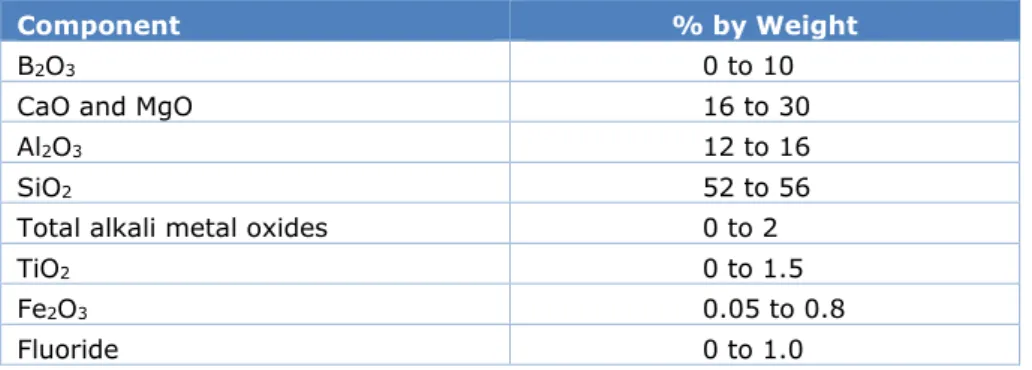
Table 5 lists the general chemical composition of continuous glass fibre (ranges). It is confirmed that these ranges in composition are also applicable to Electric Glass Fiber NL, B.V. (Gedeputeerde staten van de provincie Groningen, 2019). The norm ASTM D578-18 is the only norm for the chemical composition of E-glass for general applications and stems from the U.S. of America (Gedeputeerde staten van de provincie Groningen, 2019).
Table 5 Chemical composition by weight of glass fibres (JRC, 2013)
Component % by Weight
B2O3 0 to 10
CaO and MgO 16 to 30
Al2O3 12 to 16
SiO2 52 to 56
Total alkali metal oxides 0 to 2
TiO2 0 to 1.5
Fe2O3 0.05 to 0.8
Once the ingredients are fed into the furnace, they are melted. This is a continuous process, meaning the furnaces are running constantly and the ingredients are continuously fed into the furnace, providing a steady flow of output. Electric Glass Fiber NL, B.V. currently uses two gas-fired furnaces with oxy-fuel-firing technology (WMB, 2007). Oxy-fuel-fired furnaces use pure oxygen to combust the natural gas. This gives a cleaner combustion and prevents heat carry-over to the nitrogen. It also reduces most of the NOx emissions (JRC, 2013). The
oxygen and natural gas are fed into burners, finetuning the amounts of oxygen and natural gas for combustion. The flames enter the furnace, heating the air in the furnace up to 1600 °C. The residence time, time the melt resides in the furnace, determines the homogeneity of the melt. Sufficient residence time also removes bubbles that form in the melt. Once the appropriate residence time is reached, the forming takes place (JRC, 2013).
2.1.2 Forming
The forming stage determines the diameter of the fibres. The molten glass from the furnace flows through a series of refractory-lined, gas-heated canals to the forehearths. Each
forehearth has several ‘bushings’ that deliver the melted glass to the nozzles in the bushings bottom plate. The bushings are complex box-like structures that have a perforated metal plate (bushing plate) at the base, with several hundreds of calibrated holes (bushing tips). They are manufactured from metal alloys and are heated. The temperature is precisely regulated over the whole surface. This is done to obtain a consistent rate of flow of molten glass from each hole (JRC, 2013). Because of gravity, the molten glass flows through the holes, thereby forming filament strands that are subsequently pulled and stretched by a winding machine. The fibres are first cooled with air and water sprays, then an organic suspension coating is applied before they are drawn together and winded. The coating protects the filaments during the downstream process and ensures integration in the appropriate application. Coating materials represent only a very small portion of the total product mass, typically 0.5% to 2% (JRC, 2013). For the application of the coating, a suspension is used with around 10% solids, so further drying is necessary.
The specific composition of the fibres and coating is what differentiates the manufacturers and is therefore confidential. The fibre diameter (around 6–20 micron) is determined by the drawing speed. The drawing is controlled by electrical equipment (Gedeputeerde staten van de provincie Groningen, 2019).
2.1.3 Downstream process
After the forming stage, drying, curing and chopping takes place to produce the final product. Electric Glass Fiber NL, B.V. produces E-glass products of several varieties, depending on market requirements. Before chopping, the spindles are unwound. The fibres can be either dried and cured in ovens or fluidised bed dryers. Further chopping in short strands can take place before or after curing. The wet chopped strands and dry chopped strands are both glass fibre filaments cut to sizes of 3–50 mm. They are then prepared for transport. Heat treatment for drying and curing at Electric Glass Fiber NL, B.V. requires 15%–17% of the total natural gas consumption. The choppers and packaging machines run on electricity (JRC, 2013).
2.1.4 Recycling
Because of the required purity of the melt and end product, recycling is harder than for other glass types, such as glass wool. Simply inserting glass cullets results in too many
complications, such as impurities in the melt. Unlike container glass which is mostly sodium lime glass, continuous glass fibre uses alkali-free alumino-borosilicate glass (E-glass). Around 15%–20% of the glass throughput is lost during forming and chopping at Electric Glass Fiber NL, B.V. (WMB, 2007). Part of this waste stream is recycled in a recycling installation. The remaining waste material (around 11.5 kt/yr) is used by external parties as input material for the construction sector (MER, 2018)4.
The aim for the new furnace production line is to further optimise the process and to reduce production losses. The emission control system residues are expected to go up from 750 tonne (wet) per year to 1250 tonne (wet) per year as a result of the expansion
(Gedeputeerde staten van de provincie Groningen, 2019).
2.1.5 Waste gas treatment
The flue gases of the current furnaces are cleaned using a wet scrubber system, specifically designed mainly to remove fluoride, sulphate and dust emissions (WMB, 2007). The sludge from the emission control system and from the water treatment are transported to external facilities.
For boron containing glass (e.g. glass wool and continuous filament glass fibre), it is necessary to reduce the waste gas temperature to below 200 °C prior to abatement, whilst ensuring that condensation and the associated risk of corrosion are minimised in the emission control system. As the exhaust gas temperature from oxy-fuel furnaces is usually >1000 °C, substantial cooling of exhaust gas is required (JRC, 2013).
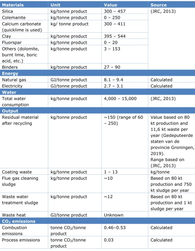
2.2 Specific energy and material consumption
Table 6 depicts the specific energy and material consumption for the production of
continuous glass fibre. Because the specific material consumption by Electric Glass Fiber NL, B.V. is unknown, a range of typical specific material consumption figures is given based on (JRC, 2013). Note that Electric Glass Fiber NL, B.V. uses quicklime instead of limestone. Water is used for cooling, cleaning, coating preparation and in some cases for wet scrubbing systems. In continuous glass fibre production, a large amount of water is needed for cooling of the bushings to reduce the temperature of the filament very quickly from 1300 °C to
ambient temperature (JRC, 2013). Also, a significant amount of water is used in preparation of the coating.
Table 6 Material inputs per tonne product (JRC, 2013)
Materials Unit Value Source
Silica kg/tonne product 300 – 457 (JRC, 2013)
Colemanite kg/tonne product 0 – 250 Calcium carbonate
(quicklime is used)
kg/ tonne product 300 – 411
Clay kg/tonne product 395 – 544
Fluorspar kg/tonne product 0 – 20 Others (dolomite,
burnt lime, boric acid, etc.)
kg/tonne product 3 – 153
Binders kg/tonne product 27 – 90
Energy
Natural gas GJ/tonne product 8.1 – 9.4 Calculated Electricity GJ/tonne product 2.7 – 3.1 Calculated
Water Total water consumption kg/tonne product 4,000 – 15,000 (JRC, 2013) Output Residual material after recycling
kg/tonne product ~150 (range of 60 – 250) Value based on 80 kt production and 11,6 kt waste per year (Gedeputeerde staten van de provincie Groningen, 2019). Range based on (JRC, 2013)
Coating waste kg/tonne product 1 – 13 kg/tonne
Flue gas cleaning sludge
kg/tonne product ~10 Based on 80 kt
production and 750 kt sludge per year Waste water
treatment sludge
kg/tonne product ~12 Based on 80 kt
production and 1 kt sludge per year Waste heat GJ/tonne product Unknown
CO2 emissions Combustion emissions tonne CO2/tonne product 0.46–0.53 Calculated Process emissions tonne CO2/tonne
product
0.03 Calculated
The specific energy consumption of natural gas is calculated to be 8.1 to 9.4 GJ/tonne product, based on the reported EU ETS emissions for 2016 and 2017 (Nederlandse
Emissieautoriteit, 2018), an estimated annual glass production of 75,000 to 80,000 tonnes, and assumed process emissions of 6% to 7%. The process emissions are low compared to literature values of 15% (Ecofys, Fraunhofer Institute for Systems and Innovation Research, Öko-Institut, 2009). However, Electric Glass Fiber NL, B.V. does not use limestone or sodium carbonate, the only carbon containing raw material at Electric Glass Fiber NL, B.V. is
dolomite. The specific electricity consumption is assumed to be a third of the natural gas consumption (JRC, 2013).
Around 80% of energy goes into melting (JRC, 2013) and 15%–17% is used for drying and curing. Part of the waste heat from the glass melt transport channels is used as energy input for the hot water boilers (for heating offices and production areas). The forming departments require a relatively high ventilation rate and therefore a lot of heating.
Electric Glass Fiber NL, B.V. can be considered as one of the more efficient plants in Europe at 0.46 to 0.53 tonnes CO2eq/tonne produced, as compared to typical efficiencies of 0.4–1.0
CO2eq/tonne. (Ecofys, Fraunhofer Institute for Systems and Innovation Research,
Öko-Institut, 2009).
2.2.1 Production equipment
The current production of Electric Glass Fiber NL, B.V. consists of two production lines with a total melt throughput capacity of around 95 kt per year (Gedeputeerde Staten der Provincie Groningen, 2015). In 2007, Electric Glass Fiber NL, B.V. applied for a permit to increase the capacity of one of the furnaces. The permit mentions furnace capacities of respectively 47 kt/year and 48 kt/year (WMB, 2007).
Both furnaces currently use oxy-fuel technology (Gedeputeerde staten van de provincie Groningen, 2019). An on-site Air Liquide vacuum swing adsorption (VSA) unit is used, with cryogenic back-up. The electric energy consumption of air separation to provide oxygen is estimated at 7% of the energy content of the fuel input (JRC, 2013). For Electric Glass Fiber NL, B.V. this would amount to 0.5 to 0.7 GJe/tonne product.
In 2017, NEG announced plans to expand the production plant, investing EUR 53 million in a new production line (RTV Noord, 2017) with a melting capacity of 120 kt per year, which replaces one of the current furnaces, increasing total production to 165 kt per year (Gedeputeerde staten van de provincie Groningen, 2019). The new furnace will be an oxy-fuel furnace with 25% electric boosting (hybrid) and is expected to have a higher efficiency than the current furnace (MER, 2018). Linde Gas will provide the oxygen from a nearby installation (MER, 2018).
The curing ovens and fluidised bed dryers are directly gas fired. For various heating purposes, there are hot water boilers installed with a combined capacity of around 10 MW (WMB, 2007), but the load factor is low.
2.3 Emissions
Emissions mainly include exhaust flows from combustion including the oxidation of atmospheric nitrogen, i.e. sulphur dioxide, carbon dioxide, and nitrogen oxides5. Furnace
emissions also contain particles from the volatilisation and subsequent condensation of volatile batch materials and traces of chlorides and metals that are present as impurities in the raw materials. The resulting dust, separated by filtration from the flue-gases, is in most cases not recycled back to the furnace, due to carryover phenomena and to the presence of aggressive/corrosive components such as sodium chloride (NaCl). Due to the nature of the forming process, varying levels of fluorides are also sometimes used in the batch, which can give rise to emissions of hydrogen fluoride (JRC, 2013).
2.4 Investment costs
Furnaces in this sector generally operate continuously for 8 to 12 years. After this, the furnace is either partially rebuilt or totally replaced, depending on its condition. Rebuilding a medium sized furnace (around 75 tonnes per day) requires an investment of around EUR 8 million. A new plant of comparable size on a green field site would require an investment of around EUR 75 million to 90 million, including infrastructure and services (JRC, 2013). An important investment decision for the production of continuous glass fibre is the melting furnace. For Electric Glass Fiber NL, B.V., a furnace with an electric boost will be added. This is an oxy-fuel furnace with a 25% electric boost (Gedeputeerde staten van de provincie Groningen, 2019) and a melting capacity of around 300 tonnes/day. The Investment for this production line amounts to around EUR 53 million (RTV Noord, 2017). This includes all expenses, such as buildings, electricity infrastructure and alterations to the downstream process.
Furnace adjustments, e.g. adding an electric boost, range from about EUR 2–5 million (JRC, 2013). New furnaces in other sectors at this scale cost tens of millions of euros.
3 Continuous glass
fibre products and
application
3.1 Product Descriptions
Continuous glass fibres can be used for a variety of applications. The main use of continuous glass fibre is the production of composite materials (glass-reinforced plastic), like
reinforcement of plastics which allows for weight reductions in automotive industries, etc. The continuous glass fibre product is tailored to meet these requirements. A rapidly growing market is the use of composites in renewable energy technologies, and wind energy in particular (JRC, 2013) . Electric Glass Fiber NL, B.V. does not produce the longer sections of fibre, so-called rovings, for these applications anymore.
Market prices are unknown. As rough a rough indication we use prices from Alibaba, which vary from EUR 400/tonne to EUR 3000/tonne for wet chopped strands (Alibaba, 2019) and from EUR 400/tonne to EUR 1500/tonne for dry chopped strands (Alibaba, 2019). Figure 4 and 5 visualise what these products look like.
Figure 3 Wet chopped strands (Nippon Electric Glass Co., 2019)
4 Options for
decarbonisation
The processes with the greatest potential for CO2 reduction are the melting furnaces and
melt feeding channels, which use around 80% of the final energy consumption. The melting furnaces, forming, curing and drying together use more than 95% of the natural gas input.
4.1 Energy efficiency, waste heat use
Process heat escapes from the furnace through the walls, the melt transport channels or through flue gases. This provides a theoretical heat supply potential. Increasing energy efficiency by using waste heat flows from the production process, to produce e.g. steam, is however difficult for Electric Glass Fiber NL, B.V. due to the lack of steam demand onsite or from nearby industry or heat network. Waste heat in continuous fibre glass production is often only used for heating buildings (JRC, 2013). Electric Glass Fiber NL, B.V. already partly applies part of the waste heat from the glass melt transport channels as energy input for the hot water boilers (for heating offices and production areas). Preheating raw materials is limited since they will show unwanted chemical reactions already at low temperatures. Possibly, waste heat can be used in the drying and curing sections, but this would require further studies.
A potential application for waste heat is district heating. The nearest district heating network being built is in the north of Groningen (Warmtestad, 2019). The distance of Electric Glass Fiber NL, B.V. to the heat net is about 10 km, the distance to the nearest urban area about 5 km. There are no concrete plans for connections to industrial sites.
4.2 Recycling
Glass fibre recycling research is ongoing and becoming a more apparent solution to reduce material losses. Electric Glass Fiber NL, B.V. possesses a recycling station. This installation is only used for internal recycling. The share of recycled materials at Electric Glass Fiber NL, B.V. is currently 6%–8%. Electric Glass Fiber NL, B.V. has stated that their goal is to recycle all their process waste glass fibres to avoid production losses.
Recycling of external streams is an opportunity for increased efficiency and therefore lower emissions. Every 10% increase in recycled glass share in the melt increases the melting efficiency by 2%–3% (JRC, 2013). This is applicable to all types of glass melting furnaces. However, externally recovered continuous glass fibre has limited applicability due to quality constraints, so for the time being, internal waste usage remains the only option.
Optimisation of the new furnace and forming sections would reduce the need for recycling internally. Incremental production improvements could gradually reduce waste streams. However, it is impossible to completely reduce waste streams, as forming and chopping will always produce some waste. The thin fibre production is sensitive and manufacturing faults are difficult to prevent.
Recycling of plastics or thermosets reinforced with continuous glass fibre has been studied widely. The recycling from plastics seem the most promising. However, there are both environmental and economical limitations to the reuse of continuous fibre glass from thermal or chemical recycling. (Oliveux, Dandy, & Leeke, 2015); Chemical recycling of reinforced plastics by pyrolysis and microwave can recover fibre with 25% loss of strength. Mechanical recycling of plastic composites does not separate the fibre, but the granulate can be used for lower quality purposes. The energy use of composites recycling processes shows very large ranges (Shuaib & Mativenga, 2016).
4.3 Electrification
All-electric furnaces use solely electricity to melt the input materials. Resistive heating makes use of electrodes that are inserted in the melt. Because of the electric resistance of the materials, the electric current produces heat, which is used to melt the materials. All-electric furnaces have a higher efficiency than fossil fuel fired furnaces. Electric furnaces are used more often in small-scale applications. For larger scale furnaces, the higher electricity price and lower lifetime largely offsets the efficiency gain, even though electric furnaces are still more efficient6 (JRC, 2013) (Worrell, Galitsky, Masanet, & Graus, 2008). Electric furnaces
can be around 25% more efficient than conventional furnaces (JRC, 2013). This depends on the type of furnace. No efficiencies could be found regarding hybrid furnaces (electric boost). All-electric furnaces for continuous fibre glass production are currently not technically
feasible, because E-glass has a low alkali content resulting in very low electrical conductivity (JRC, 2013). This limits the heat transfer to the melt. Electric boosting, however, is possible. Electric Glass Fiber NL, B.V. is currently expanding its capacity by building a new furnace, which will use 25% electric boosting. The total investment is EUR 53 million (RTV Noord, 2017) for a 120 kt/yr furnace and other required capacity expansion of current equipment (forming, dryers, electricity supply, etc.) (MER, 2018). For this capacity increase, more electricity will be consumed. An additional 10 kV substation and several transformers will be built to handle the increase in electricity demand (MER, 2018). Part of the Electric Glass Fiber NL, B.V. investment is a 3.5 km new cable to a substation.
The actual performance of the new configuration at Electric Glass Fiber NL, B.V. still has to be determined. Assuming an energy consumption of 7 GJ/tonne of melt (JRC, 2013), for 120 kt the furnace alone would require at least 0.75 to 0.8 PJ per year, around 0.56 to 0.6 PJ natural gas and 0.19 to 0.2 PJ electricity. With the electric boost, demand for electricity at Electric Glass Fiber NL, B.V. will roughly double. The required additional capacity would be at least 7 MW7.
For Electric Glass Fiber NL, B.V., electric heating could also play a larger role in the other natural gas applications. It could be applied to the sections after the furnace where the melt is transported to the bushings. This section requires around 5%–10% of total gas
consumption. The required temperature to be maintained in the melt is at least 1300 oC. The
share that can be electrified has to be further investigated.
Electrification may also be relevant for the rest of the gas consumption (around 10%–15%), mainly curing ovens and drying sections, that require hot air with temperatures of up to 200 oC. Whether the heat use of these processes can be further optimised and the remaining
energy demand electrified, requires further research.
6 Although the difference in efficiency decreases as the efficiency of fossil fuel furnaces increases with scale. 7 Note that the actual energy consumption of the new furnace might be lower.
4.4 Hydrogen use
During the past two years, hydrogen has gained more attention in the mineral wool and glass industry (Verheijen, 2019). The option that is considered is hydrogen combustion instead of natural gas. To be considered a decarbonisation option, the hydrogen has to be produced from electrolysis using renewable electricity (green hydrogen) or from natural gas in combination with CCS to mitigate CO2 emissions (blue hydrogen). Using hydrogen can
have the advantage of cleaner combustion and no CO2 emissions. For 100% use of
hydrogen, oxyfuel burners could be used to combust the hydrogen with pure oxygen, instead of air, to avoid nitrous oxide (NOx) formation. Challenges lie in the higher flame temperature
at 2200 °C compared to 1900 °C for natural gas (The Engineering Toolbox, 2003). Questions that still need to be answered are how the furnace design needs to be altered, especially when looking at the burners, and how the different fuels will affect the melting process and melting efficiency. The risks of using hydrogen also needs to be investigated further. The availability of affordable hydrogen produced from renewable electricity (green hydrogen) or hydrogen produced from natural gas in combination with CCS (blue hydrogen), is currently a limiting factor. The current natural gas infrastructure can potentially be refurbished to allow for transport of hydrogen.
As combustion of hydrogen using oxy-fuel hydrogen burners only produces water, only CO2
emissions from process emissions would remain, in theory resulting in an 95% emission reduction during the melting stage.
4.5 Upgraded biogas
Upgraded biogas has virtually the same composition as regular natural gas (mainly consisting of methane) (Cermáková, Mrázek, Fliegerová, & Tenkrát, 2012). This can be directly injected in the natural gas grid without compromising the quality of the natural gas. Whether or not this will affect the behaviour of the melting furnaces is unknown (Verheijen, 2019). Since it has virtually the same composition as natural gas, no major adjustments to the furnace are expected to be needed.
When using only upgraded biogas for both the glass furnace and the curing oven, the only emissions that would be left are process emissions. The total emission reduction would be 93% to 94%, assuming process emissions of 6% to 7%.
5 Discussion
Reducing production losses by optimising the processes of the furnace and forming sections, reduces the energy consumption per tonne of continuous glass fibre. However, production losses from forming and chopping cannot be prevented completely due to inevitable occasional manufacturing faults.
The main energy consumption in continuous glass fibre production comes from the melting furnaces and melt feeding channels. Together they account for around 80% of the final energy consumption.
Electric Glass Fiber NL, B.V. is currently installing a new furnace which will use 25% electric boosting. Full electrification of the melting furnace is, however, technically not feasible because the low alkali content of E-glass results in a very low electrical conductivity and therefore limits the heat transfer to the melt.
The possibility to switch fuels from natural gas to hydrogen or bio methane depends on the developments in supply of these two energy carriers. For hydrogen further research is also required to determine what required furnace design alterations are needed, due to the different flame characteristics.
The potential for carbon capture and storage is currently limited as there are no nearby facilities for transport and storage.
References
Alibaba. (2019, February 20). Dry Fiberglass Chopped strands. Retrieved from Alibaba: https://www.alibaba.com/showroom/dry-fiberglass-chopped-strands.html
Alibaba. (2019, February 20). Wet Glass Fibre Chopped Strands. Retrieved from Alibaba: https://www.alibaba.com/showroom/wet-glass-fibre-chopped-strands.html Cermáková, J., Mrázek, J., Fliegerová, K., & Tenkrát, D. (2012). Replacing Natural Gas by
Biogas - Determining the Bacterial Conatamination of Biogas by PCR. Acta Polytecnica, 52, 33-38.
Ecofys, Fraunhofer Institute for Systems and Innovation Research, Öko-Institut. (2009, November). Methodology for the free allocation of emission allowances in the EU ETS post 2012 - Sector report for the glass industry .
Gedeputeerde Staten der Provincie Groningen. (2015). Omgevingsvergunning verleend aan PPG Industries Fiber Glass B.V. ten behoeve van het wijzigen van een bestaande inrichting bedoeld voor de productie van glasvezel. Groningen.
Gedeputeerde staten van de provincie Groningen. (2019). Besluit mer beoordeling uitbreiding productiecapaciteit.
Gigler, J., & Weeda, M. (2018). Routekaart Waterstof TKI Nieuw Gas .
Gough, P. J. (2017, May 26). PPG sells fiberglass operations to Nippon Electric Glass. Retrieved from Bizjournals:
https://www.bizjournals.com/pittsburgh/news/2017/05/26/ppg-sells-fiberglass-operations-to-nippon-electric.html
JRC. (2013). Best Available Techniques (BAT) Reference Document for the Manufacture of Glass, Industrial Emissions Directive 2010/75/EU (Integrated Pollution Prevention and Control). Seville: European Commission Joint Research Centre.
MER. (2018). Aanmeldingsnotitie belsuit MER productiecapaciteit Nippon Glass Westerbroek. Nederlandse Emissieautoriteit. (2018, May 2). Emissiecijfers industrie 2013-2017. Retrieved
from Nederlandse Emissieautoriteit:
https://www.emissieautoriteit.nl/onderwerpen/rapportages-en-cijfers-ets/documenten/publicatie/2018/04/03/emissiecijfers-industrie-2013-2017 Nikkei Asian Review. (2019, February 20). Nippon Electric Glass Co., Ltd. Retrieved from
Nikkei Asia: https://asia.nikkei.com/Companies/Nippon-Electric-Glass-Co.-Ltd Nippon Electric Glass. (2018). Nippon Electric Glass Europe. Retrieved from
http://www.negeurope.nl
Nippon Electric Glass Co. (2019, February 20). Glass Fiber. Retrieved from Negeurope: https://www.neg.co.jp/en/product/fiber/
NPAL. (2019). Electric Glass Fiber NL. Retrieved from http://www.npal.nl/bedrijven/electric-glass-fiber/
Oliveux, G., Dandy, L., & Leeke, G. (2015). Current status of recycling of fibre reinforced polymers: Review of technologies, reuse and resulting properties. Progress in materials science, Elsevier.
RTV Noord. (2017, October 30). NEG investeert 53 miljoen in glasvezelfabriek Westerbroek. Retrieved from RTV Noord: https://www.rtvnoord.nl/nieuws/185408/NEG-investeert-53-miljoen-in-glasvezelfabriek-Westerbroek
Saint Gobain Vetrotex. (2019). Fiberglass Manufacturing. Retrieved from Vetrotex Textiles: https://www.vetrotextextiles.com/technologies/fiberglass-manufacturing
Shuaib, N., & Mativenga, P. (2016). Energy demand in mechnical recycling of glass fibre reinforced thermoset plastic composites. Journal of cleaner production, Elsevier. The Engineering Toolbox. (2003). Flame Temperature Gases. Retrieved from The Engineering
Toolbox: https://www.engineeringtoolbox.com/flame-temperatures-gases-d_422.html
Verheijen, O. (2019, January 30). Interview with Celsian. (R. Krijgsman, & M. Marisid, Interviewers)
Warmtestad. (2019, February 20). Warmtenet Noordwest. Retrieved from Warmtestad: https://warmtestad.nl/duurzame-energie/warmtenet/
WMB. (2007). Vergunning wet milieubeheer verleend aan PPG industries fiber glass. Worrell, E., Galitsky, C., Masanet, E., & Graus, W. (2008). Energy Efficiency Improvement
and Cost Saving Opportunities for the Glass Industry. Ernest Orlando Lawrence Berkely National Laboratory.